advertisement


DAC Kit - what else do I need?

Status
Not open for further replies.
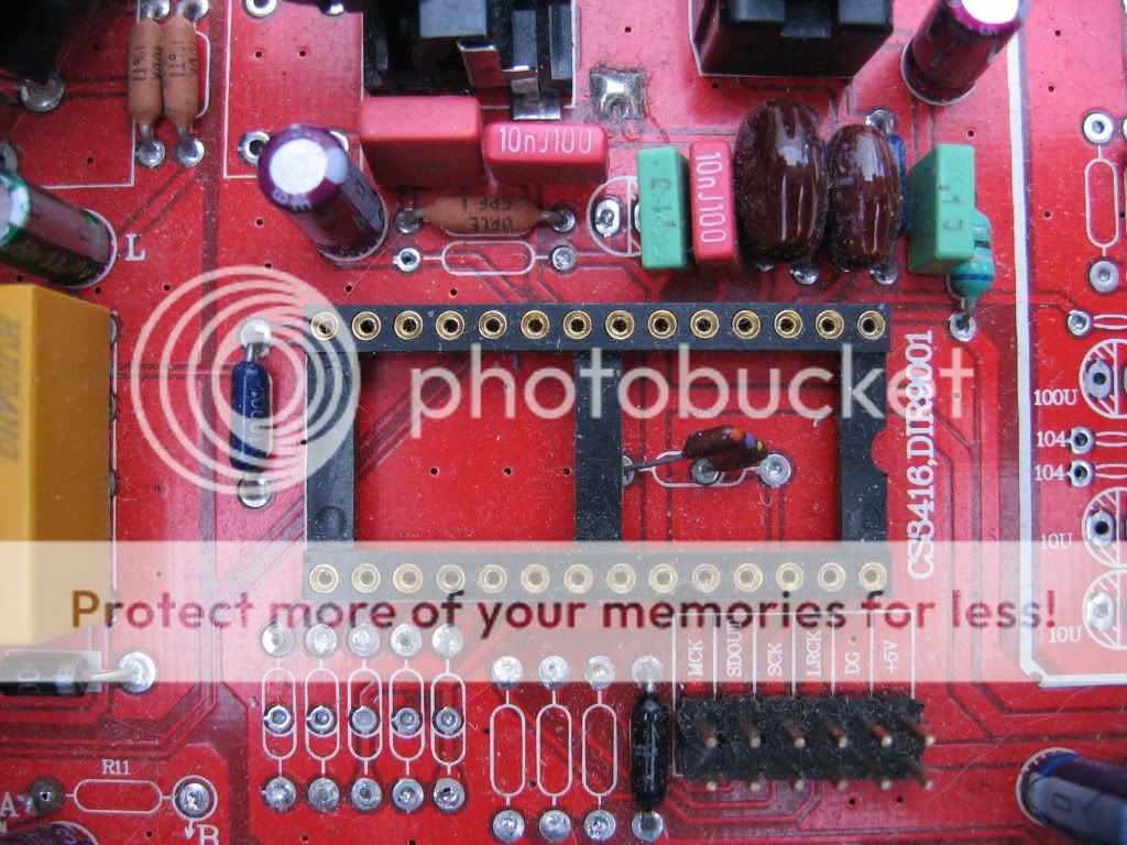
Yes you did thank me, no problem mate. Am I right that you repaired a broken pin on the adapter? Very steady hands you got there. Be very careful about removing the module from the sockets - no rocking them out. Maybe when you get the extra pins from ebay you could remove the dodgy pins by snipping them at the plastic insulation and replacing them entirely. If it ever goes tits up again just ask for my spare adapter set.

Just looked at the CS8421 datasheet and it is very greedy. Is it just a simple case of using a different low noise pass transistor with a higher Hfe (2SC170 etc?) For now I'm sure a reg booster will do fine. Also think about replacing the 3.3V reg on the sampler with a booster, just re-use the 3.3v reg on the new booster. It worked for me, a bit fiddly and careful when attaching to the SMD pads, they are a bit flaky. Definitely no sitting on the module! (you'll never live this down...:D)
 
I was very lucky in that the adapter pins sunk into the cushion and only two broke. They were pins 1 & 28 and are not used J Some were bent but straightened ok.
The decoupling caps had to be redone and it was the caps that caused the problem were they were soldered directly to the chips smd legs in so much as they lifted a pad and tore off one pad and pin L
Unfortunately my hands shake like a leaf and my eyesight is poor but has been so for some years so I have learned to work around this buy the use of head strap magnifying lens, good lighting and lots of jigs and fixtures.

Regarding the CS8421 up-sampler, why not just feed the whole chip at 3v3 and do away with its on board 5v0 to 3v3 reg?

Right now I am thinking of S/PDIF receiver supplies and fitting a flea for the receiver duty, this load is nice and low so a standard flea would do nicely.
That would reduce my 95mA to perhaps 85, another 5 for the led and the current stack up with what the data sheet predicts.
I only have a flea with the pass transistor mod spare so would have to build another on up.
There again the bypassed flea could be operating more efficiently due to the AD797 now operating in pretty much constant current mode. The BC547’s limit power to about 80Ma, might be worth swapping both BC547’s for BD140’s

Maybe a STR or ALWSR are more suited for this receiver,

I am not sure of the SQ since putting it back together with the reg booster corrected to bom. Bass seems to have become a little rounded and lost its incision. May be my decoupling on the converter did not go back correctly or maybe I just had an elephant ears night.

Tony
 
Well things are not going so well. Lots of good news, bad news.
I took the S/PDIF receiver out to investigate the pin outs.
Good news this adapter seem to be wired in order unlike the converters adapter.
Bad news I snapped the pin 28 from the adapter.
Good news I managed to fix it with one of Rich's turned pin sockets and a resistor lead.
Bad news I measured pin 21 VL expecting 5v0 but got 3v3 :confused:
Good news, I gave up for a while and had a listen instead.
Bad news, SQ is rubish, slow, laboured and lacking impact. I blamed Lobo for his booster :)
Good news, so I removed the booster for investigation, it seemed fine.
Bad new, I refitted the boooster and found 9v6 on its output rails.
Good news, I expected this to explain the crap SQ.
Bad news, whilst investigating around the booster I realised I had left the 317 reg setting resistors in place were they were removed and STR's / fleas fitted.
Good news,its a quicky to whip them out and my current loads drop slightly.
Bad news the booster was still high output.
Good news, I have spare 317's so I fitted a new one and did away with the booster.
Bad news still high volts.
Good news, found 317 adjust pin to ground set resistor was open circuit, bad tracks / pads. Fixed with a jumper wire below the board.
Bad news, only 1.25 volts from the re now.
Good news, 317 pin to upper setting resistor open circuit, another jumper under the board and hey what do you expect... 5v0 :)
Got to end this on a double goody
Good news, SQ is back. :D

What a fiasco, you could not make this up :)

So I have no booster on the reciever circuit, just a raw 317. SQ is still the best its been. This seems to imply the fleas are outpacing the boosters in the performance stakes, well they should realy.

Just need to remember to fit a heat sink to that 317 before the board melts...


Rich, another fav if you please. I could do with a link to the pins that fit under the adapter boards.
 
Which pins do you mean Tony - The actual turned pins that fit into the DIL sockets? The ones Giga use have slightly smaller diameter than the ones you have just ordered from ebay. I don't have a link for them but i'll do a search for ya.

Don't forget that I've got spare CS8416 and CS8498 adapters. Just say if you need them.

Fair bit of trouble there, it's those bloody solder pads... they are shite
 
Hi Rich, could not believe the agrovation was having :)
Playing well again though.

Regarding the pins, its the legs fastened to the adapter board.
The one you sent me will fit the dil sockets but are not quite the same thing. I was going to use the ones you already sent as male / female plug / scket things. I think you are doing the same, looks a neat trick. But I now need adapter board legs.
 
I cant guarantee that these will be exactly the same but they are very close:

http://www.jprelec.co.uk/store.asp/c=458/Turned-Pin-SIL-Headers

http://www.technobots.co.uk/acatalog/Shop_Front_Turned_Pin_SIL_PCB_Header_20_way_1338.html

They need to be turned pin, square will not do.

It might be a case of checking the datasheets and getting a micrometer out.

Hey Rich you sorted it before although I did not realise it.
What you linked to before
http://cgi.ebay.co.uk/Turned-pin-SI...etTopBoxes&hash=item1c0b47a295#ht_1081wt_1138
They fit the adapter boards, It did not gel with me that I was buying both male and female parts. They arrived today, fast service and they are just wat I need.
Many thanks
 
This site contains affiliate links for which pink fish media may be compensated.
Excellent. I wondered why you wanted more pins!

The ebay ones are much, much tougher although a bit tight in the DAC DIL sockets. If Giga had used these ones you wouldn't have had so much trouble.

:):)
 
Excellent. I wondered why you wanted more pins!

The ebay ones are much, much tougher although a bit tight in the DAC DIL sockets. If Giga had used these ones you wouldn't have had so much trouble.

:):)

Hmm, you sent me just the socket end, I did not pay attention to what I was ordering :) Least said the better

Got the booster back into the up-sampling position on the 5v0 rail now
We thought it also feeds the SP/DIFF 5v0 VL pin 21 but my reciever has 3v3 on pin 21?

Anyone have a good photo of a virgin Gigadac.
It may be a help to some guys if we post a picture with all the bits marked up.
I could do this but I dont have original photos.
 
Suffolk Tony did some good pics in post #36:

http://www.pinkfishmedia.net/forum/showthread.php?t=77490&page=3

The S/PDIF receiver gets 5V on pin 1 I think. Pins 6, 21 and 23 are linked and get 3.3V from the 3.3V reg nearest the center of the board. You need to remove the CS8416 adapter to see the pins linked.

Good idea about labeling the DAC parts.

Actually I'll save you the bother. Here's a pic of underneath the S/PDIF adapter:


IMG_2125.jpg
 
The S/PDIF receiver gets 5V on pin 1 I think. Pins 6, 21 and 23 are linked and get 3.3V from the 3.3V reg nearest the center of the board. You need to remove the CS8416 adapter to see the pins linked.

Pin 1 is not used
 
Has anyone got a template for the connections to the DAC? I've ordered one and I need to get a case organised if possible.
 
Has anyone got a template for the connections to the DAC? I've ordered one and I need to get a case organised if possible.

Welcome to the club, it wont impress at first but it does not take much to get it singing.

Sorry I cut the back panel out with out a template.
 
Rich, package recived.
Thanks

Cool, no problem.


Has anyone got a template for the connections to the DAC? I've ordered one and I need to get a case organised if possible.

Good man, welcome to the club!

Do you mean the AC connections from the transformer?

Have a look at the supplied manual, second picture in:

https://dl.dropbox.com/u/6496254/new 24.192 dac setting information/CS4398 DAC2 192KHz.pdf

For an exact fit I recommend a modushop maggiorato 230 x 280 mm case.

Edit: ah Tony beat me to it, you meant the back panel cut outs. Download this word document. It has a diagram with connector centres etc:

http://www.mediafire.com/?kde6f37526j533i
 
Thanks folks for the copies of the manual etc. I think the dac will go in a modushop case. I am addicted to the damn things.
 
OK, I'm thinking of creating a Wiki space for this DAC and the mods. Could take time. I think a few PFM projects could do with a Wiki.

I need permission from all who have contributed to this thread to use pics and info. So especially Bemused, Sam and Suffolk Tony for their pics.

It will be a community space that can be edited and added to by all.

I will need to collate and consolidate the information and the stages of modification.

We'll see how it goes.

Rich
 
I've nicked a few bits myself and stuck it on a word processor file.

Thanks for the kind welcome.

Mike.
 
Status
Not open for further replies.


advertisement


Back
Top