advertisement


regulator booster

Hey Mike, what happened to this little beauty:

http://www.pinkfishmedia.net/forum/showpost.php?p=862516&postcount=17

Would love some of these.

I might come back to this at some point and offer a group buy. It ran into trouble when I tried to make the PCB generic so that It would accept any type of TO-220 reg. I wasn't happy with it basically. If I did it again I'd probably look into using SMD caps and resistor to make it smaller. I'd also do a range of PCB's to suit different types of regulator. I think I'd only need to do 3 different PCB's to suit most reg's. Your not the first to show an interest so I'll go over it again sometime soon then put up an 'Group-buy intrest check' thread in the near future.
 
Electrolytic is 10uF Elna cerafine (I have no KZ's), Film cap is 2.2uF wima MKS. Transistor is BC550C. Resistor is 10K

When suggesting the KZ I was referring to the on-board cap at the regulator output.

The 10uF & 3.3uF cap's in the RB circuit should probably be Tantalum for the 10uF and film (or low ESR lytic such as Oscon) for the 3.3uF.
 
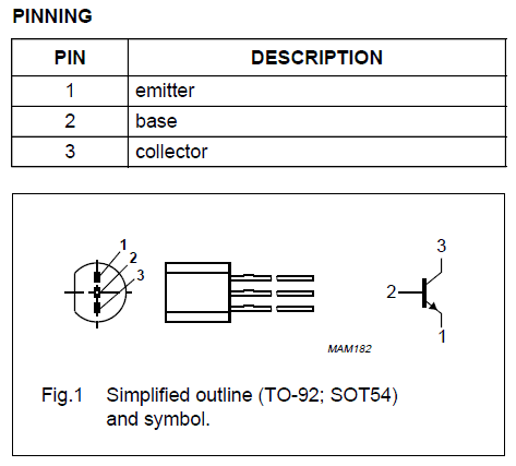
Another thing. Check the pinout of the 550C and compare to the 547C. Its back to the drawing board I think :D If you need a hand PM me and I'll send my phone number so you can give me call.

Ok Mike will PM you about this.

In the mean time I have ordered BC547's and BD139's to cover all bases!
 
I just built a LM317 reg booster for LoBo using BD139 and 100uF Tant for high current use. Beow is a photo of the reg.

parts008.jpg


Here is a diagram of how to build one for LM317 regs. The diagram is based on the low current version using BC547C and 10uF Tant. For the high current version be aware that the pinout of the BD139 is different.

317regbooster.gif


BD139
A010914.jpg


BC547C
BC547C.gif
 
And since the hfe of the BD 139 is pretty dismal, you'll almost certainly need to reduce the value of R1 dramatically to make it useful, else you'll get a huge forward voltage drop.

The forward voltage drop across the transistor is roughly [0.7v + (Ic/hfe)*R1].
So if you need to pull 100mA with a transistor with hfe of about 100 at 100mA (as for BD139, see the datasheet) you can expect a voltage drop of about 0.7 + (0.1/100* 10K), say 10.7volts...

Fortunately with that 100uF cap you can reduce the 10K to 1K with no real penalty ;)

(hence why the flea used a BC547C , and only loaded it with ~10mA)
 
Why wasnt that mentioned earlier! :D

LoBo, if your reading this you'll have to replace the 10K resistor mate ;)

EDIT: It was sort of wasnt it. Martin, so this reg just needs a 1K and all is well?
 
Sure, providing the raw supply is high enough provide the necessary ~2v or so of additional voltage drop ahead of the reg's minimum dropout voltage - in other words, for (say) 100mA output the voltage difference across the present regulator will need to be about 5v or more to guarantee all is well.

There are other ways round if not.
 
Would it be possible to use a BC547C with a 43v supply ? I'm using HV LM317s to supply 36v @ 10 to 12 mA. I can see the voltage differences are well within the operating limits when the circuit is working but I'm concerned that startup will give the BC547 a fright.
 
The voltage isnt really the problem (but for that example a BC546C would be a better choice, you are right at the 45v limit of the 547!)

What does matter not going mad with capcitance after the transistor at the input to the Vreg - so that the inrush current at raw psu switch-on doesn't blow the transistor. The reg will be happy with even just 0.1uF (100nF) at its input; 1-4.7uF will be more than enough.
 
Martin,

Thanks for the advice about the capacitance ( I only have the two transistors I need!)
I'm going to try the zener diode trick too.

Thanks for all your efforts to make PFM such an interesting and friendly place.
 
I'm want to try this regulator booster but have a few questions. From what I've read the 3.3uF cap and the 10K resistor form a RC filter with a ~5Hz corner frequency. Wouldn't a lower value resistor and a higher value cap with the same corner frequency be better? I've read that lower valued resistors are less noisy than higher valued ones.

I want to install female headers on the PCB to enable quick and easy regulator swapping, any thoughts on that?

I want to upgrade the 7805 that feeds the clock of my CD player. ATM there's a bog standard 'lytic cap on the (to be replaced) 7805 regulator output. Should I leave it there or would an upgrade to OSCON be preferred when I install this regulator booster?

Thanks!
 
Using larger values of R and/or C increase the time it takes for the regulator to reach its output voltage. Depending on the application yes larger R or c could be used to lower the cutoff frequency. Not sure if there's any audible improvement, depends on the application, I would think very minor though.
 
I want to upgrade the 7805 that feeds the clock of my CD player. ATM there's a bog standard 'lytic cap on the (to be replaced) 7805 regulator output. Should I leave it there or would an upgrade to OSCON be preferred when I install this regulator booster?

Thanks!

Hi Beftus

Generally a bit of ESR is a good thing on a regulator output the help keep it stable and thus 'quieter'. On my reg boosters I found Nichicon MUSE KZ to work very well on the reg outputs. Otherwise a simple Tantalum should work well as Martin Clark suggests.

If there is lytic decoupling cap further down the chain right at the clock then it might be beneficial to use an oscon here. But on the regulator output avoid low ESR.
 
Tants should be fine, and bigger is better within sensible limits. 10uF, 22uF, 33uF - all are fine. As long as the voltage rating is sufficient you should have no worries.

Hello

I am just about to start making one of these regs. I have some 47uf tants in stock I was wondering if they would be ok?

Thanks

Richard
 
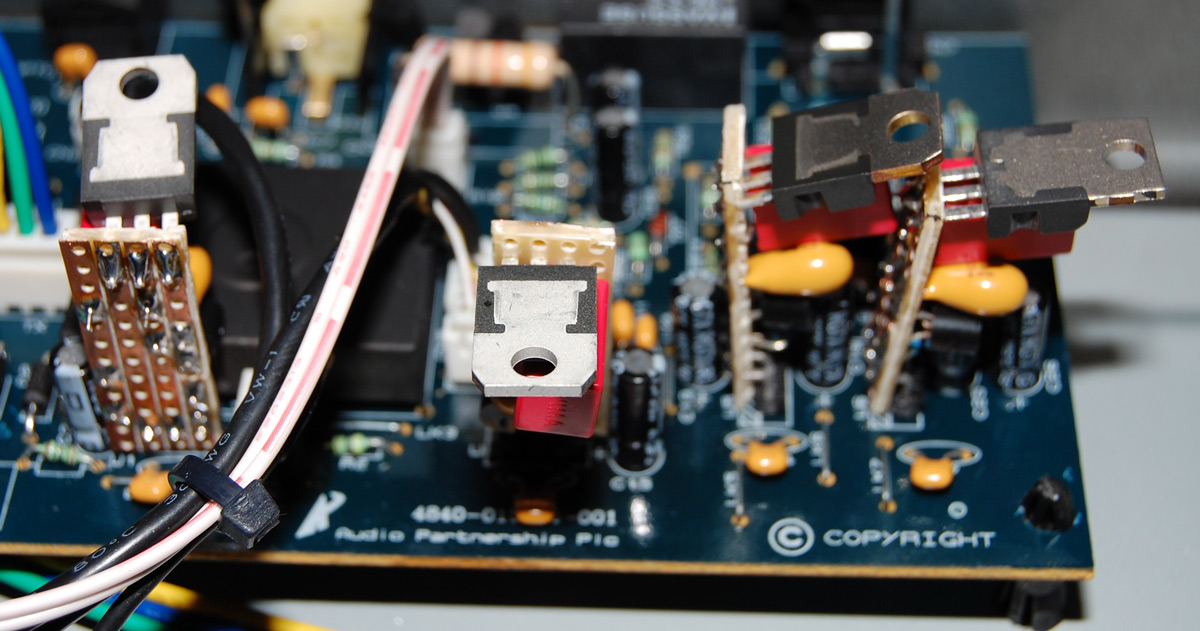
I finally got around to making my boosters. I replaced all the regulators (7805,7815,7915) in my Azur 540C cd player.

DSC_0013.jpg


How does it sound now? A very nice improvement in soundstaging, the treble really sparkles without being harsh. Worth it? IMO, yes these homebrew regulator boosters provide a pretty cheap upgrade.
 
Hi,

I'm coming to this late but I'm going to be building some 317 based regs this weekend and thought I may as well add the vbe/gyrator to them.

I'm a bit confused though, is the vbe/gyrator just the bc547, 10kr and 3.3uf combination or is the following 10/22uf from input to gnd also part of it?

Regards

Pete
 
Only the transistor and the two components (R, C) feeding its base. You should really always use a small cap at the input to the 3pin reg anyway.

Note the combo you quote only suits use under, say, 50ma.


advertisement


Back
Top