advertisement


Naim CDi servo board problem

iqpi

Member
Hello everyone I've just bought a Naim CDi with issues (that how the previous owner described it). Up on powering the unit up I noticed the motor spins immediately and fairly fast CCW, it just spins and spins no matter what I press, with or without CD. The laser tried to focus and stay in inner-center position but the warp speed made it chucked out an error.

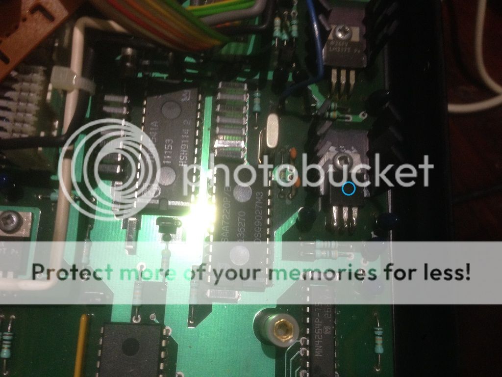
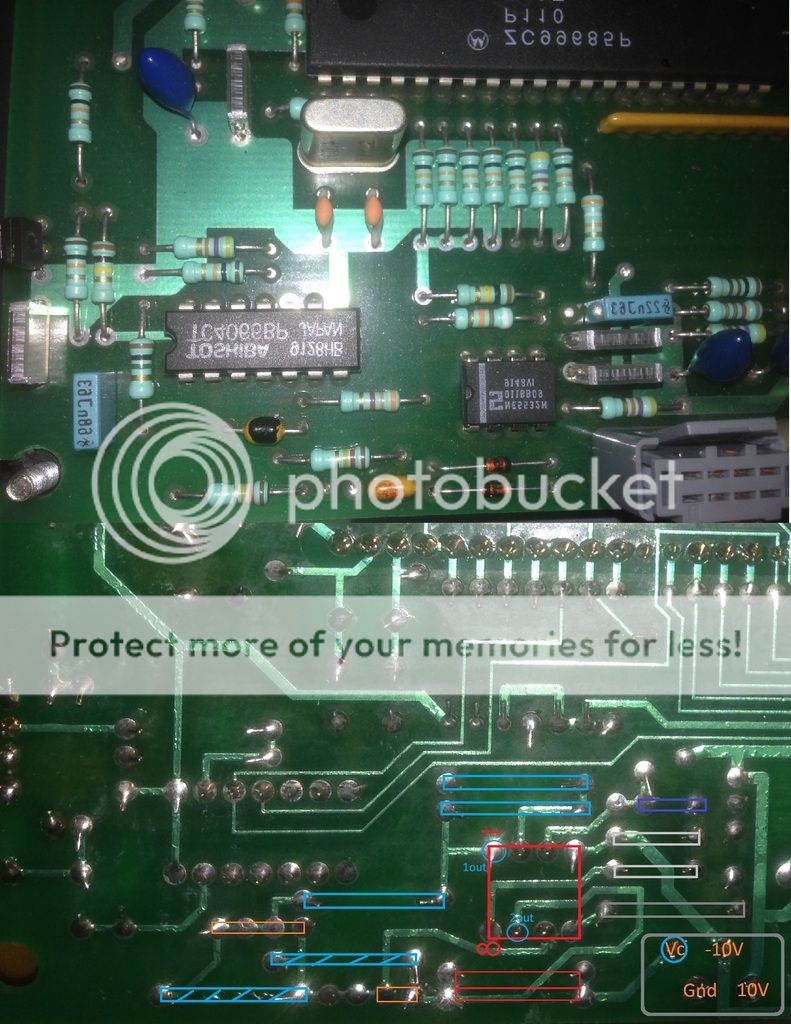
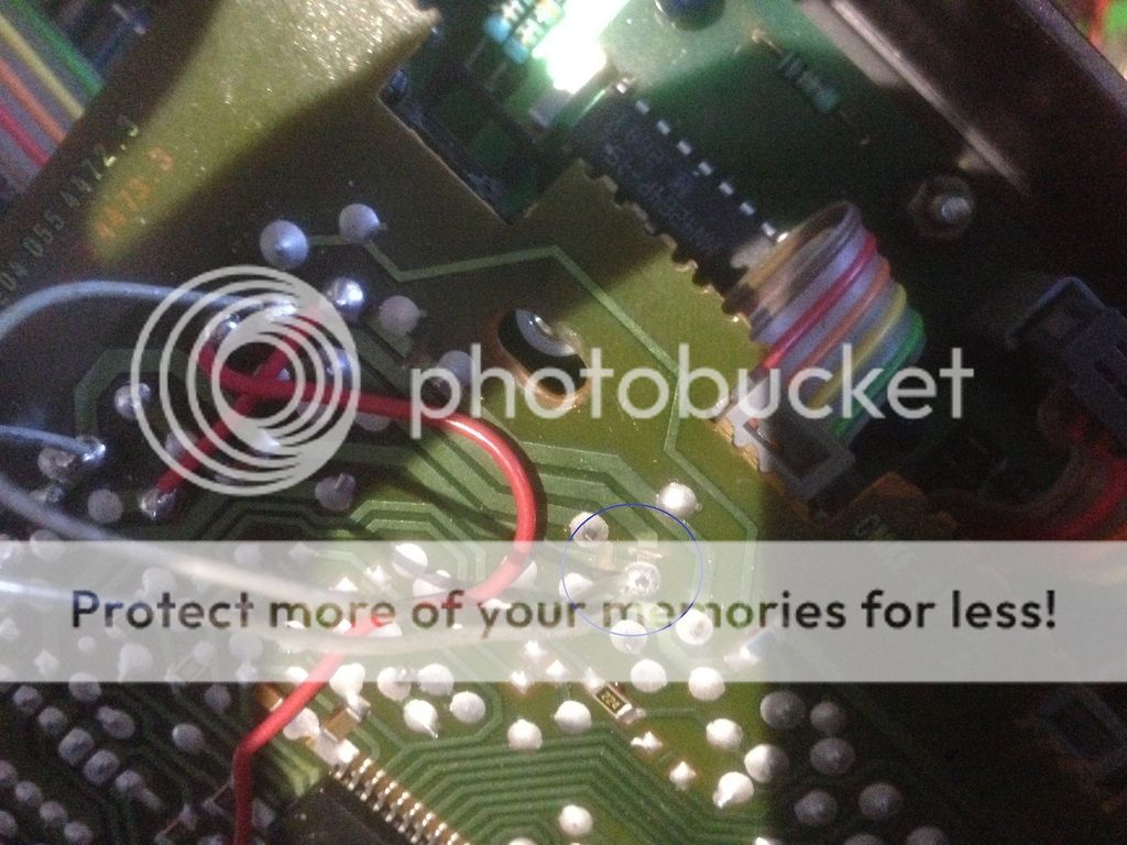
Further inspection revealed that for some reasons someone tried to scratched out two electrical traces. One of the traces lead to the 220uf caps the other leads to the lid switch-connector and the red wire that goes to the collector of transistor 8c338. Right now I have reconnected the traces with solder wires (temp fix) and fired it up. The speed is the same but this time the laser goes all the way out to the edge and stays there and no focus whatsoever. To put insults to injuries I think I smelled that beautiful electrical fume coming out from one of those 220uf caps :(

I'm not sure what I should do next..any help is greatly appreciated.
Aaron

IMG_1631_zpsvmdj3rwa.jpg


servo_zpsb2qhhfml.png


IMG_1634_zpsehexbrwt.jpg
 
Naim modified these boards to have a better earthing arrangement, and to enable the lid switch to force a reset and enable the laser current. The boards are cheap paper resin type that has its own particular smell. By putting back the trace you may have shorted out something.

The motor will spin uncontrollably if the clock is missing so that's the first place to look.
 
You are right. I have checked against google and confirmed that is manufacturer mod, I've removed the connections and will replace the two 220uf caps.

This servo uses the following three ICs:

a. TCA0372dp2 Dual Op-Amp - driving the Laser Focus?
b. TDA8809t Radial Error Processor - signal processor for motor?
c. TDA8808t Photo-Diode Processor - signal processor for laser control?

Would it be correct to say the 8809 is not receiving the clock signal or itself-is-fried?
Aaron
 
I agree with MJS, it seems like it has a problem with the clock signal.

Do you have access to an oscilloscope?
 
Ive removed the connections and replaced the all the caps on the servo board. In the process I found a bad 1ohm resistor. Bridged it with a piece of wire of approx 1ohm and sure enough it behaved like the first time I turn it on.

I will go to the local shop for the resistor tomorrow as I dont have any 1ohm laying around, will a 1ohm 5% 0.25W ok as replacement?
Aaron
 
The turntable motor is fed from the main board - albeit with feedback from the servos. But if it is running uncontrollably then there's a clock issue on the main board - usually the crystal oscillator near the DAC.
 
Thank you for your inputs so far MJS & Mike P.

Unfortunately I dont have access to a oscilloscope.
The motor is running fast but with constant speed and there are two crystal oscillators on the main board. One is 4Mhz and the other is 11.2896Mhz, which one is likely to be the culprit?
 
The 11.288Mhz crystal is the clock for audio; the other just runs the control microprocessor.

Check there is a full 5.0v supply to the SAA7220 for a start - this is also the clock generator, and the clock signal is also sent from pin 9 to the servos. The SAA7220 draws a lot of current, about 220mA, so runs hot - could simply be the LM317 5v reg for it isn't performing as it should after all these years.

No scope? pfm DIY has a couple available to borrow! Depending on where you are, there may be one of those in orbit near you :)
 
Thanks Martin. I will check pin 9 of thr 7220 IC and the LM317 reg. Are we talking about the LM317 next to the 7220 as pictured?

IMG_1654_zpscqkcjvhn.jpg
 
Not sure though it looks logical (I don't have a CDi) but it'll be easy to check - pull-up datasheet for the 7220, and the +5v supply, Vdd, is pin 24 (the one on the corner nearest philips logo) - see you have 5v to the ground plane there with the player powered up. As it is with the player unpowered your DVM continuity /resistance check will soon identify the reg that feeds this pin - just check for 0.x ohms to the middle pin - the output - of the LM317s nearby.
 
Alright here are the results : VDD of 7220 gets 4.9V and the LM317 Vout gives 4.9V and Pin 9 of the 7220 gives 1.7V

By the way, I live in the land of the kangaroos so I guess I'm a bit too far for that scope.
Great site. Great people.
 
That all looks about right.
Hmm.
There will be a series resistor somewhere between the clock send from SAA7220 to the radial processor clock inoput ( I don;t have the datasheet to hand) - check with the dvm (player off) you see continuity i.e. a sensible resistance (likelihood, order of 100ohms between the two relevant pins. If so, thr route for thr clock signal is intact and either(i) thr TDA80xxx is having a problem or thr clock isn't running at all (pretty unlikely, tbh, and seeing the crytal and two ceramic tuning caps adjacent look intact in the pic above (might want to check this with a loupe for no cracks in solder joints)
 
It's worth checking all the power supplies. The tantalum capacitors age quite badly in this player as it runs fairly hot. All the LM317 tabs are at output voltage. 18v thereabouts on the analogue supplies and 5v for control and 9v for servo/motor. The negative supplies are -18 analogue, -15 DAC and -9v servo/motor. As you look at an LM337 (-ve regulators) the right hand pin is the output.
 
I have traced pin 9 to 7310 IC and lost track. The datasheet and continuity check revealed that pin 26 is connected to pin 9 of 7220.
I have reflowed solder of the crystal os and the two caps, made no difference.
Aaron

IMG_1735_zpspg14a1f1.jpg
 
Is there any chance the crystal went bad? I might take it out and observe the motor again.
 
Crystal out and motor behaved exactly the same.

The motor board has four wires to it. Vc, Grnd, -8V, 8V printed on the board, I've measured:
Vc : 4V
Grnd : -
-8V : -10V
8V : 10V

I think the Vc is a Voltage Control that tells the IC (LM324N) on the motor board whether to speed up or slow down the motor since the voltage is at constant 4V and the speed of the motor is constant.

I took the Vc pin off and now the motor is not spinning, could this be the voltage that tells how fast the motor should spin? Mayve we work backward from here and see what is giving the 4V signal?

IMG_1744_zpsgilv64wf.jpg
 
I might have something.

The connector to the motor board has Vc connected to the NE5532N (as pictured). The NE5532N has 2 outputs from pin1 (1out) and pin7 (2out).
This is the measurements of the pins with power on:
1 (1out): -4.3V
2 (1in-): -
3 (1in+): -
4 (Vcc-): -10V
5 (2in+): -
6 (2in-): -
7 (2out): 4.3V
8 (Vcc+): 10V

So pin 1&7 has constant power out. The power out from pin 1 (-4.3V) got cancelled to 0V by the pin7 (4.3V) at resistors in blue stripes. The 4.3V from pin7 of course went on to the motor board via Vc pin.

I thought the laser has to focus first and if there's a disc present then the spin signal will be sent to the IC but this IC seems to putout constant +- 4.3V no matter what. Is the NE5523N is fried or is there something more sinister at play?

Aaron

IMG_1742_zpskslo1j5b.jpg
 
I've isolated the NE5532 op amp from any inputs except for the Vcc+ and Vcc- but the problem still persist. I've even replaced the NE5532 and the LM324 four the transistors (although the old one tested ok) on the motor board but still no cigar.

What do you guys think? The problem lies with the motor board? or the main board?


advertisement


Back
Top