Mike Hanson
Trying to understand...
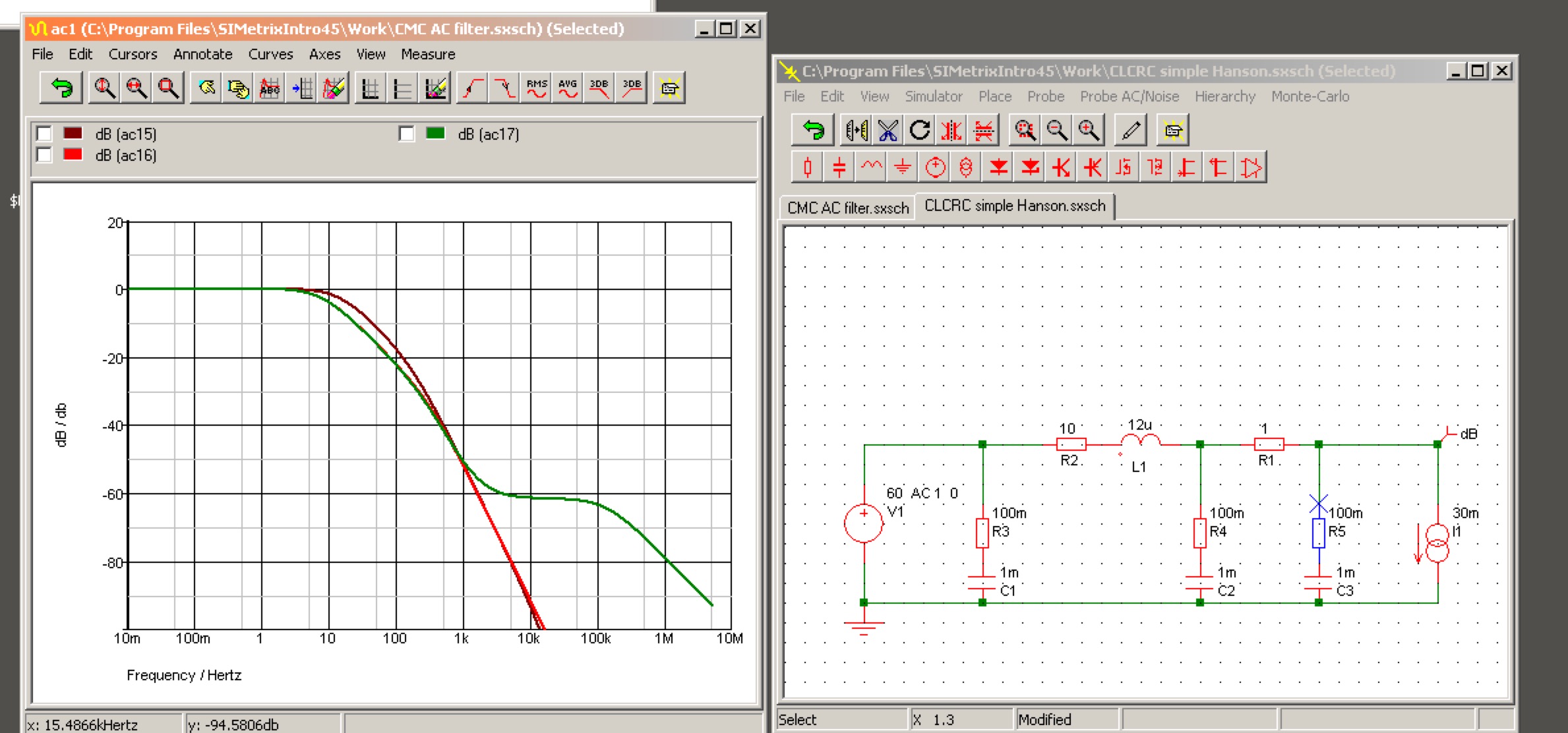
I put the smoothing module together on some strip board (a.k.a busboard). I was able to get both channels on the single board. I started with a basic plan for the layout, then marked it out for one complete channel, then just enough to keep my bearings on the second. To make the capacitors fit nicely, I used two strips for the ground running down the center:
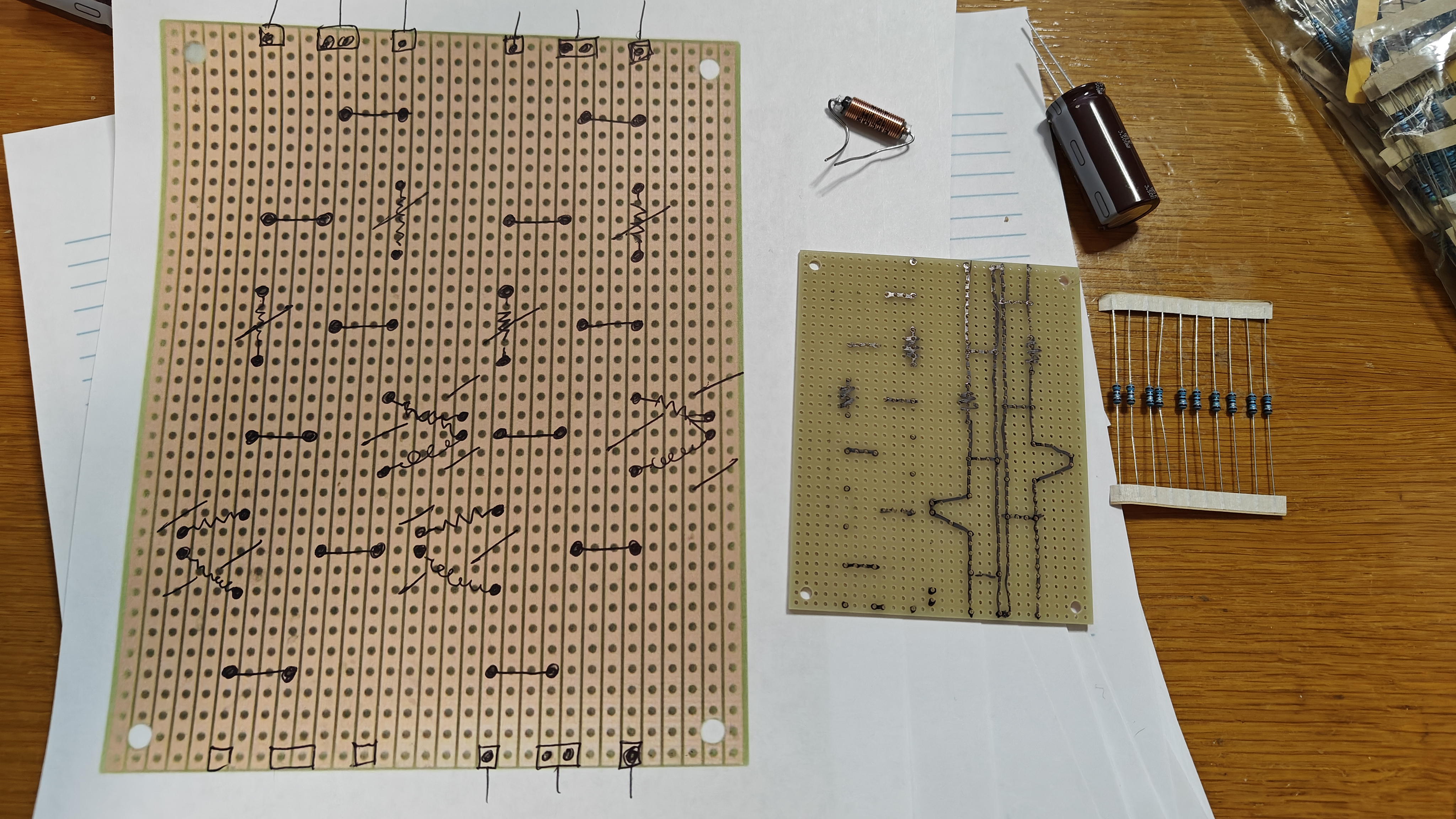
I installed the resistors first. The 1R is on the upper area, oriented vertically. The 10R is horizontal, enabling the series connection with the inductors.
Then I added the capacitors and inductors:

Due to the size of the inductor, it sits at an odd angle, reaching over its series resistor:

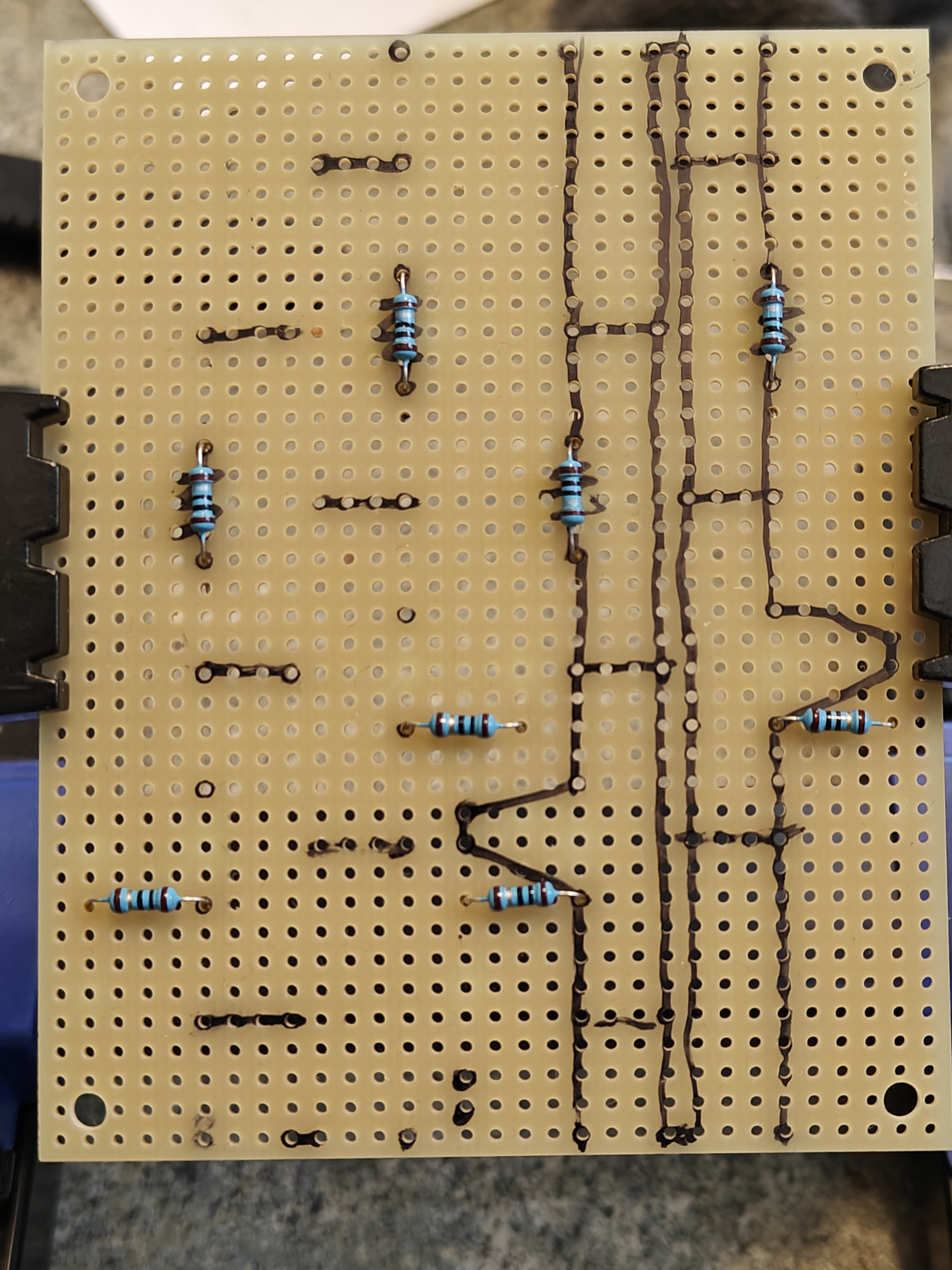
Then I decided the reinforce the tracks by adding a bit of solder. Given the low current, they probably didn't need it, but I also figured it would visually clarify the circuit, for me to double check that everything was fine. I also created more breaks in the tracks, to ensure that all that solder didn't cause a short circuit:

It's not the tidiest soldering job, but I probed about and everything seemed fine. I soldered a bunch of wires to the inputs and outputs to finish the job.
Finally, I hooked up a little transformer with 12VAC secondaries plus an Avondale FWB rectifier module. Using my Variac for safety, I confirmed that no magic smoke came out, and both sides are acting exactly as expected.
Thanks for your guidance, everyone!
I installed the resistors first. The 1R is on the upper area, oriented vertically. The 10R is horizontal, enabling the series connection with the inductors.
Then I added the capacitors and inductors:
Due to the size of the inductor, it sits at an odd angle, reaching over its series resistor:
Then I decided the reinforce the tracks by adding a bit of solder. Given the low current, they probably didn't need it, but I also figured it would visually clarify the circuit, for me to double check that everything was fine. I also created more breaks in the tracks, to ensure that all that solder didn't cause a short circuit:
It's not the tidiest soldering job, but I probed about and everything seemed fine. I soldered a bunch of wires to the inputs and outputs to finish the job.
Finally, I hooked up a little transformer with 12VAC secondaries plus an Avondale FWB rectifier module. Using my Variac for safety, I confirmed that no magic smoke came out, and both sides are acting exactly as expected.
Thanks for your guidance, everyone!