advertisement


How much capacitance?

Mike Hanson

Trying to understand...
I was going to use an existing HackerCap to power the input stage on an Avondale NCC300 (Voyager config). I just realized that the capacitors in the HackerCap are rated at only 63VDC, so I need to do something different.

Additionally, the caps in this module are 10,000 µF, so 60,000 µF total for the bank of six. There are also 12 mH inductors between each bank (CLCLC). That seems like far too much for the input stage, which I've been told will draw about 30 mA.

My first thought was to swap in 100VDC caps with a lower capacitance, but removing those is a bit of a hassle, and I could reuse the existing HackerCaps for another project.

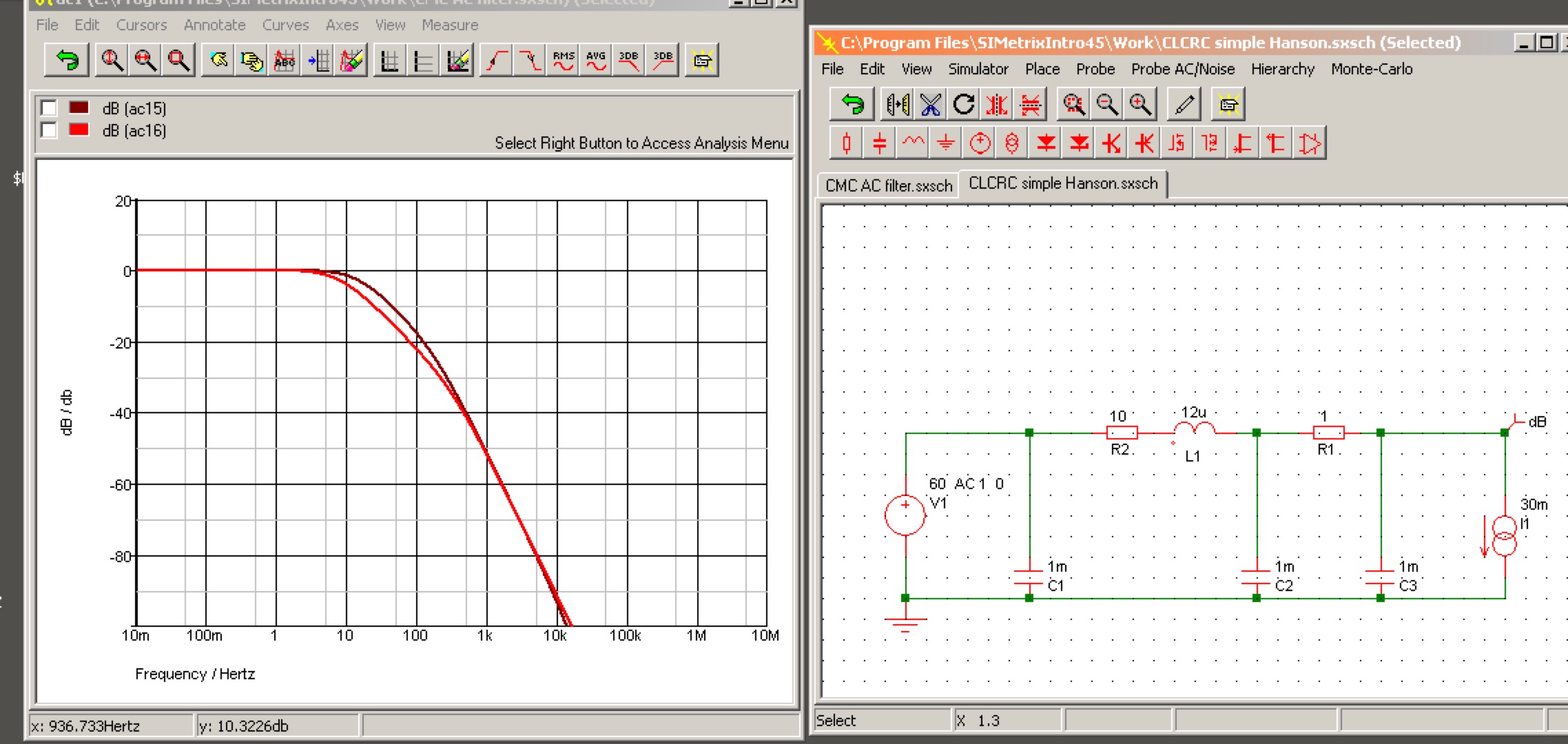
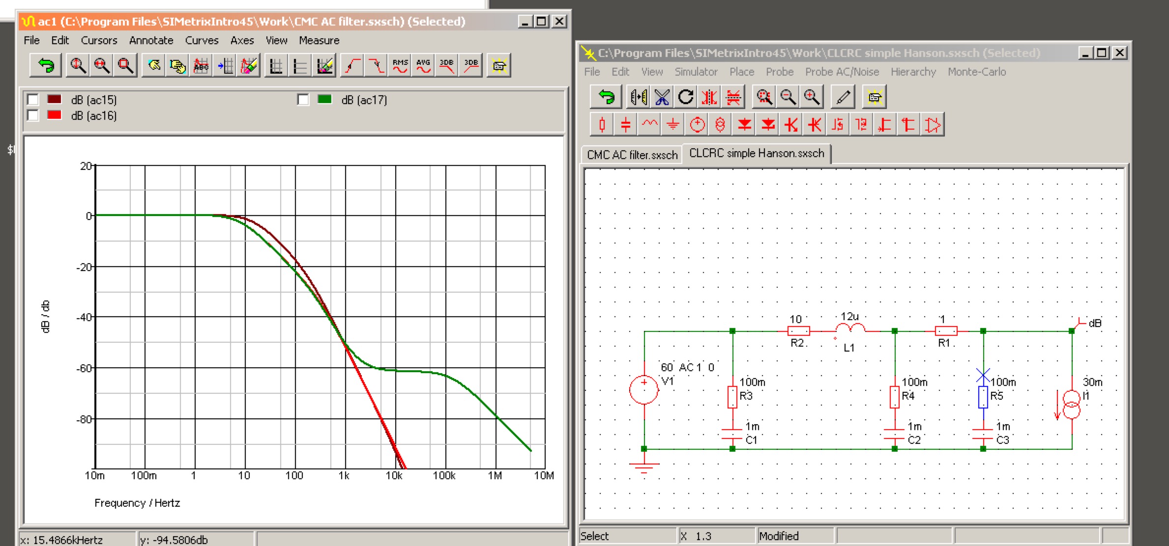
Instead, I thought I might put something together with busboard, using 4 capacitors instead of 6, again with 12 mH chokes between the two banks (CLC). I have an existing Avondale FWB rectifier, so I don't need the rectification onboard.

Assuming that's a feasible approach, I'm pondering what size of caps to use. Would 1,000 µF be sufficient per cap? Or perhaps 2,000 µF for the first bank, then 1,000 µF after the choke. The total would be 6,000 µF, just one-tenth of the existing HackerCap.

Any thoughts?
 
I hope you mean uH, not mH (micro, not milli...) else it'll ring like a bell at LF...

Anyway, basic physics sez:

CV=IT

(... let's ignore the effects of the little inductors, because it does not affect this... only the output spectrum unless they also have significant resistance compared with the load current - which might be useful to you - )

You propose:
  • 30mA load = 0.03A
  • 3 x 1000uF caps in parallel, per rail = 0.003F
  • 60Hz Mains AC so with bridge rectifier t = 0.00833s
- NOTE: input voltage doesn't matter. Just time, load current, and capacity.

So close-approximate V drop under load = ~ IT/C
= [0.03*0.008s] /0.003
= c 83mV ripple arising from the load;

That's more than good enough on a 'front-end' raw supply' with 40dB LF feedback or more, ~ 4uV resulting output ripple, and that - is utterly in the weeds, for Naim/Lin topologies. At the point where actually the whole-build layout, & wiring implementation , will have larger effect, by far.

..and this also reveals the purpose of using a little R-L-C in any order on such a supply: it is to reduce the pass-through of HF mains harmonics/noise, to make that result above 'stick' over the whole audio spectrum ( and above) - because the available feedback (== PSRR) will fall at min 20dB/decade, above a fairly -low frequency, related to ensuring the amplifier's stability. Using (adding) a little L, a little R, helps that landscape, a lot.
 
On your situation, my concern would be more the ESR than the total capacitance.
You want those capacitors to be fast.
OTHO, capacitors of these sizes are rather cheap so too big is better than too small.
But eh, I’m not an expert !
 
Thanks, all. I've ordered some capacitors, and I'll post a few pictures once I've lashed something together.
 
Herewith the front end PSU (bridge rect is not on the PCB) for my Sugden Au51p. As far as I can tell the equivalent output stage PSU is a 10,000uF capacitor.

EDIT: It may be of interest that the datasheet for the pass transistor shows an absolute maximum collector power rating of 900mW. It's in a TO-92 package.

cap_mul by plybench, on Flickr
 
Last edited:
Herewith the front end PSU (bridge rect is not on the PCB) for my Sugden Au51p. As far as I can tell the equivalent output stage PSU is a 10,000uF capacitor.

cap_mul by plybench, on Flickr
Interesting. In this case I need +/- rails. Can I just stack two up end-to-end (positive to negative) like capacitors, with my real ground running down the centre?
 
NB - there is a slight 'gotcha' with such things, explored a long time ago here. The output impedance at LF of such a thing is a function of

1. the resistance in series with the base from the raw rail (the 1k6 value above, dominates) [lower is better, for LF low impedance - if that matters, and for your use it does not ]
2. the capacity of C2 [large like this is good, it reduces current noise. Dont go mad though - the 1-2s delay to full voltage rise this example already provides might cause other issues - you want teh front end to be in control at start-up]
3. the output current drawn - far smaller effect than the dominating two items above. [ BJT Emitter output resistance ~ 26mv/ (output current in mA) ]
4. There are things like the value of Rbb', but that's in the weeds in comparison.

- and you need to 'size' things so you don't overheat the transistor - how much current, at max Vdrop across it? Consider the effect of that slow start again...


Using say a small power type, with a Hfe of maybe 100 at 20-30mA, the above circuit will have a resistive output impedance of about 15-18ohms at DC, that drops to half that at 1 ohm, and stays...something like that.

The nice thing with this approach is - so long as a the transistors base is driven via a resistor as shown, sufficient to stop it oscillating (which such things otherwise, love to do without such!) - the output is resistive. Very forgiving characteristic, and utterly-consequential if it is supplying a constant-current 'front end' LTP as is typical in Lin -type power amps - Naim & Avondale's take on the Naim approach, and a very many others.


(ETA: becasue 'constant current' == very high impedance as a load)
 
I'm having fun pondering this, but given my n00b electronics design skills, I'll likely stick with the basic CLC supply for this build.
 
whatever L you choose, add an ohm or so in series with it to damp it properly - post your likely values (including series R of the inductors) , and its easy to calculate.
 
Last edited:
Is the Avondale vbe for front end supply not just the big brother of the above?
This is the amplifier board for 1 channel of the Sugden. The highlighted components are the equivalent of the mini6/VBE pair used in a Voyager style Avondale amplifier. :D


Sugden Au51 Front end PSU by plybench, on Flickr

Oh, forgot - the diodes of the bridge rect are on the PSU board (bottom left and bottom right, in sets of 4)

psu_comps by plybench, on Flickr

BugBear
 
whatever L you choose, add an ohm or so in series with it to damp it properly - post your likely values (including series R of the inductors) , and its easy to calculate.
I'm planning to use three 1,000µF capacitors per side (3,000 total for both rails). I was originally going to do it CCLC, with a 12µH inductor (40mΩ series resistance). It sounds like you're suggesting CCLRC, or would it be better to go with CLCRC? And how big should that resistor be?
 
Mike

I would go 3300uF L 3300uF

That should be fine. And I think thats the sort of thing Avondale use on their front end power supplies. The draw on the front end is less than 30 ma on the NCC300, closer to 15ma. If your going to use an Avondale Cap board you could try 2 and then 3 caps per side see if you hear any difference
One thing you might want to consider with the 300's is I know Les had 6.8uF Epcos on the main power rails plus a 1uf wet tent in his last builds to squeeze the last ounce out of them. From pics he posted on his forum I also saw a 1uf polypropylene across the bias transistor as well
All things you might want to try
I have still yet to build my 300's up yet so I cant advise (my efforts so far gone into the SE range as you know)
 
Sorry - missed the earlier reply
If you go with the suggestion above, all good stuff, then a your 12uH, 40mOhm inductor will be pretty much critically-damped, without any added parts.
However - zero harm in adding R in series with the L value, an ohm on its down will help in the LF-into-midrange zone from rectification up to where the inductance adds -40dB/decade of frequency of attenuation - which is above 1kHz. in round numbers. 9with 1 ohm inserted, noise from rectification is about -20dB at that point)

I use this same approach for my headphone amp, with different values (and 10x the current draw). It is very effective.
Thanks for the reply, Martin. That makes perfect sense.

I've been doing a bit of reading, and many are saying I would benefit from a RC filter in there, so essentially CLCRC. (Some actually contend that the "L" isn't really helpful for a low current supply, but oh well.) I was thinking of using 10R, resulting in only 0.3V drop across the resistor (when drawing 30mA). The resulting low-pass filter would have a cutoff frequency of about 16Hz, attenuating the 120Hz ripple by about -18dB.

This is all using the 1000 µF caps that I have on hand, along with a 12 µF inductor for the "L".

Does this make sense?
 
Yes it does, but with a second decoupling section, the maths gets rather more complex, because it potentially becomes a set of coupled oscillators: so let's simulate instead.

c.3mins in simetrix, and this is the implementation to go for. CRLCRC - for the values you propose.

CLCRC%20_MikeH.jpg


The interesting bit is - you need the larger resistance in series with the inductor, else C1-L1-C2 are significantly underdamped as a set, and you get a spike just to just above 0dB at 1-2Khz (not illustrated, and not nice - it actually represents a /gain/ in noise!) As the circuit is drawn you get the very nice, smooth red curve - -80dB right in the audio mid-range, that's a great result; in fact -20dB at 120Hz for your mains rectification is well worth having. R2 at 10ohms is only dissipating c 10mW, so anything will do.

Incidentally - swap the values of R1 and R2 - you get the darker curve; when on paper you might think - oh, what difference can that make.
Either, would work fine for your application; my pref would be as illustrated.

HTH!


PS incidentally - the source on the left is '60vDC, 1VAC ripple at all frequencies simulated'. Th DC value won't have any effect on this sim, and the 1VAC component may be large, or about right for a big amp on occasion - but makes scaling this easy.

Note of caution on ambition, obvs - the effect of the small dc resistance of the inductor is utterly-negligible in comparison, so not shown, neither are the effects of ESR in the caps (which will limit ultimate roll-off, but make little difference to this quick illustration). Yet -the latter does mean that the practical limit will be c -80~90dB, if your layout and implementation is good: but that's still a lot of suppression of raw supply noise, for very little effort and cost.
 
Last edited:
Just to revisit this - here's a quick review of the same as above, but with ESR of 0.1ohms per cap added, crudely. Which might not be unreasonable for very cheap caps after many years service.

At that - c. -60dB is about where it flattens out. And at that, is still very-much worth having, since it means 1/1000th the voltage noise on teh raw supply. Fit, and forget.

ATB!

CLCRC%2BESR%20_MikeH.jpg


advertisement


Back
Top