advertisement


Got Ticks and Fleas?

13mh13

Pi-s Artist
My Flea became a tick because:
-- a tick is an arachnid (8-legs)
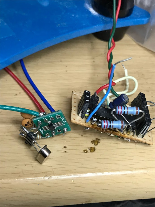
-- the orig. Veroboard Flea I hacked in 2007 now has two 4-pin oscillators (2x4=8), each can be quickly switched in between.
-- The Dream Project is based on an original, strange NOS Philips/Magnavox CDP that was made for 8-pin tda1543

The photos below are a continuation of another exterior thread that was de-serviced by "those in charge".
Some of this the following content is also based on postings here on PFM. E.g. see:
https://pinkfishmedia.net/forum/threads/flea-to-saa7210-remove-22k-resistor-for-x_out-x_in.280206/

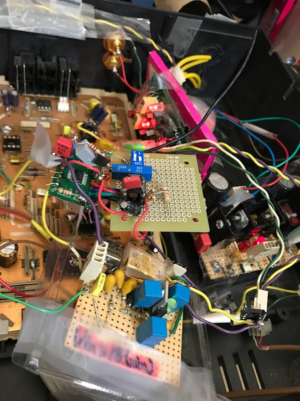
Some of what you're looking at in the photos below:
Orig. Magnavox CDB2000 (Dream Project, in situ) --> CS8421 + TDA1545a --> Rudolf B/Jocko Homo IV (Dream Project, in situ).

The LARGE FONT stuff is per a "plug-n-play" feature I had wanted for a very long time. It allows one to keep as much of the upstream and downstream (in situ) stuff in place while still allowing me to rapidly switch out, say, dac chips. The plug-n-play is not a hot/live feature (to protect electronics), but does allow one to swap out DACs (or DF+DAC, ASRC+DAC, etc) in under a minute. This should please some objectivists.
In the exterior thread, you'll note I had experimented with several other plug+play modules, all built on Vero.
The CS8421 + TDA1545 was an important module experiment as it allows one convert from I2S to EIAJ with a single SSOP device. All prev methods that I'm aware of (including ones that I have prototyped) have been messy glue logic using multiple 74hc devices. Various CS841x receiver chips -- like classic CS8414 -- also allow for I2S to EIAJ conversion. However, the CS841x receiver chips do not allow for I2S input. Only SPDIF.
With the CS8421 + TDA1545, using quite a bit of resistor-based pin-hardware logic control/hacking of the CS8421, I've got both I2S-to-EIAJ conversion and the goodness of ASRC -- all on that small SSOP device. Cool. Alas, for NOS purists, the CS8421's minimal output is 2x. Ahh ... but sonics ....
As reported in ...
https://pinkfishmedia.net/forum/threads/flea-to-saa7210-remove-22k-resistor-for-x_out-x_in.280206/
... the sonics are very, very good.

And it was resourceful use of the orig Flea that sat retired since 2009.
And Martin may recognize one of his LM317 tracking -pre-regs (it's a dual +/- 15v version bult in 2007; currently using just +15v for the Rudolf IV)
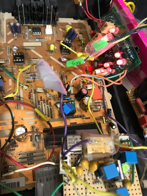


BONUS:
Below is a TDA1387 module, rapidly swapped out, and now playing as a NOSer (under 30sec).

 
Further notes ...

Some questions one might ask about orig. post projects (and my attempts at answers!!) may be:

Q: What DAC chips or digital chips are you concentrating your efforts on for your messy "dream" projects?
A: Mostly DAC chips that are >20 yrs old. Multi-bits and hybrid multi are very interesting (like under-rated tda1305). And many are still cheap on Ali. But overall used prices have been skyrocketing on many classics and even newer chips, like the PMD100. I also like to mix things up, in combos never used in other models or DIY projects. Like the weird CS8421 + TDA1545 coupling. And Also: Found some relatively inexpensive classic Sony over-samplers and 1-bit dacs on Ali -- including the ones used in the coveted ES series -- so I'm curious about sticking them in the Philips dream machine, just for kicks.

Q: Low-cost Chinese PCB kits "diy" and modable-whole-box units are avail., many using classic dacs (tda1541, tda 1387, tda1305, etc). So why bother with the messy diy Vero's?
A: That's true! And that's where many of started -- myself included . But:
-- The Chinese kits don't incorporate ALL the tweaks and possibilities I'm now interested in. Like my the weird CS8421 + TDA1545 coupling. Or even weirder DF1704 + dual TDA1545 coupling (see the DIYA thread for that project, that had many doubters, but I got it to work, and now is one of my fave-sounding weird combos). Yeah ... many of these combos really get into the weeds of complexity, even absurdity. That's how it goes!
-- The Chinese kits may incorporate under-performing ancillary devices/sections. I like good Amanero for USB . Flea clocks. Tent or other HQ osc's or crystals. Discrete output or I/V stages. Tracking pre-regs. Etc. And, of course, use of boutique or good-brand parts sourced from reputable distributors like Digikey, Mouser, Newark.
-- my messy Veroboard "dead bug", direct-wire approach actually allows trace lengths to be tighter than PCB, using quality, thick, US-made wire and Kester silver solder.

...and ...

-- diy is more fun than ordering from a ready-to-go from Ali. I think that's why you are here:
Home > Forums>discussion>d.i.y.
 
There aren't that many of us here, and those who may have an overlap with your work above may not even know the thread is here. (FWIW, what you're doing here isn't something that I've done myself).

Also, you're demeanor is rather off-putting, making it less likely that people want to engage with you.
 
Jesus H. Christ!
After all that work into this thread, is that the best reply you can come up with?

Apologies 13mh13 if my attempt at sad humor put you off. I guess my smiley face also went over your head as well. Carry on then.
 
Also, you're demeanor is rather off-putting, making it less likely that people want to engage with you.
If by that you mean I:
don't consume alcohol and have a good/low-calorie diet;
do get 8rs of sleep, and exercise, daily;
and don't watch the telly or movies;
and mostly stay off my iPhone and especially social media (including myriad Forums and Groups, which are essentially filter bubbles and echo chambers) ...
... then, yer right, toots ... ;) My "demeanor is rather off-putting" ... and I am entertained by your inconvenience, matey ;)
Oh ... and one more thing ...
 
Um, maybe you are approaching the image given in the manual, page 12, 17 years ago. What load did you have on the output of the clock in all three tests ?

In any case it isn't the top and bottom of the waveform that matters, at all; it is the rate and consistent-timing of the transition between the two. Stuff that cannot be measured with an oscilloscope, because its internal timebase will be several orders of magnitude more ...jittery.
 
The scope image on p12 looks just okay, and similar to my test, with that spike. My load for the Flea (as in my scope test) is the Philips CDP itself and the scope probe.
For the SN74VLC design, I have 100R buffer, as noted in the AAC thread, and the "load" is the scope probe. The datasheet for SN74VLC does note an R_load and C_load but does not specify values.
I have not done freq-domain analysis on either osc. That is, SA-based metrics, so -- yes -- I don't know about jitter of both clocks. And there are audible-only effects for sure, regardless of time or freq analysis.
All that said, the little SN74VLC -- in a very small device, on that protoboard -- did very, very well on the old analog o'scope. The magic of the SN74VLC lies in the "Y" output which is quite unique. My congrats to TI for having developed such a device -- 19 years ago, now!
 
: )

Getting really good results on a scope though, requires a lot more bandwidth in the probe - and 'scope - than you think - and that's a problem. There is a simple if fiddly DIY probe run-around that I'll post later when I have more time.

Bottom line is - if you are using a standard 60/100mhz probe, on an 10+MHz clock those ripples are all lies, artifacts of measurement technique. The pic I showed referenced above is one case in point. calculate the timescale of one cycle of the ripple you see; compare with your probes bandwidth (noting, that that loop 0v clip-on return at the probe tip is the mother of all evil here, worsening matters over stated performance) - you'll quickly realise the display is not to be believed. Rhetorical question: how many harmonics are required, to accurately represent a square wave of X Hz? Then look at the measurement bandwidth needed for an accurate representation of even 1Mhz, say... and convert upwards. Standard probes are NFG.*

But again - the ripple is not what matters - it's the regularity of the transition between states,where enhanced clock performance in jitter-sensitive applications, lies: needs be down to a few 10s of pS for 16 bit audio. (There are a few, well - considerable) subtleties beyond that, but none we'll likely even approach on a DIY basis.

* your example pics, any of them: the first cycle of ringing on each example is in total <1/10 one cycle of notional 11.3Mhz ish. Right, so a 'standard' probe with unrefined application is going to show you 120Mhz, accurately? Is it hell...

Probe technique becomes everything, very quickly. Read Linear Technology AN-47 by Jim Williams; the appendices on measurement technique are a model of clear - and very enjoyable! - technical writing.


PS: do keep-up the enquiring & critical questions prompted - that's a healthy process for us all.
 
Last edited:
: )

But again - the ripple is not what matters - it's the regularity of the transition between states,where enhanced clock performance in jitter-sensitive applications, lies: needs be down to a few 10s of pS for 16 bit audio. (There are a few, well - considerable) subtleties beyond that, but none we'll likely even approach on a DIY basis.
If you are suggesting that it is the regularity and spacing (and its TEMPORAL exactness and precision), then yes ... the geometry of the square is not related. And, indeed, my small clock may well be under-performing in that respect (compared to Flea or Tent or even dCS!!).
Do you know of a way to measure those "gaps" in the square wave train? Say over a period of 1ms, 1s, etc. ? Get an average of the events? See/measure any "stretching" or "contracting" of the train? Analogous, perhaps, to a long, heavy freight train that lengthens and shortens as it is braked or accelerated .
 
Yep, but in only round descriptive terms - it is way beyond us here: requires at a minimum a really good double-balanced mixer, a precision clock source, a really good vector network analyser, maybe two; and knowledge of how to characterise , then exploit such expensive equipment: and serious VHF chops to even begin-with ...


...whereas, I draw lines, and colour them in for a living - i.e. no help at all %}
 
Yep, but in only round descriptive terms - it is way beyond us here: requires at a minimum a really good double-balanced mixer, a precision clock source, a really good vector network analyser, maybe two; and knowledge of how to characterise , then exploit such expensive equipment: and serious VHF chops to even begin-with ...
...whereas, I draw lines, and colour them in for a living - i.e. no help at all %}
Why don't you post your "beyondness" at place capable of understanding it? The AAC community might be able to go "beyond". Or is that some sort of patent/IP protected stuff from your day(dream) job ??? ;)
About "vector network analysers", I have both a NanoVNA and TinySA. I may also be acquiring an E1DA Cosmos soon. So I can go there as necessary ;)
 
I'd post links except the forum, and knowledge is sadly long-gone.
Hobby VNAs not nearly going to get there.
Or you got banned--like me everywhere, everywhen, everywhy ;) Was it diyhifi.org?
Disagree, up to a point, about "Hobby VNAs" ... they were designed from the get go -- like the Cosmos -- to emulate the big-$ HP's and Agilents and Audio Precision's and R&S. ... So hobbyists and DIYers could have much of the same cake, and eat it too!
 
Ever heard of the concept 'all the gear/ and no idea' ..?

It's rife in every aspect of modern man's endeavours.

Whereas ; Faraday and esp J C Maxwell & later Oliver heaviside got to the root of things - without so much an AVO meter.
 
Or you got banned--like me everywhere, everywhen, everywhy ;)

No - never banned anywhere, despite absorbing criticism, usu in a positive way, developed & defended opinions etc. Even the drive-by crap you usually, have-long, shed in your wake.

You might reflect well there, on how that happens to you; what the common-factor is; the why.
 
: )

Getting really good results on a scope though, requires a lot more bandwidth in the probe - and 'scope - than you think - and that's a problem. There is a simple if fiddly DIY probe run-around that I'll post later when I have more time.

Bottom line is - if you are using a standard 60/100mhz probe, on an 10+MHz clock those ripples are all lies, artifacts of measurement technique. The pic I showed referenced above is one case in point. calculate the timescale of one cycle of the ripple you see; compare with your probes bandwidth (noting, that that loop 0v clip-on return at the probe tip is the mother of all evil here, worsening matters over stated performance) - you'll quickly realise the display is not to be believed. Rhetorical question: how many harmonics are required, to accurately represent a square wave of X Hz? Then look at the measurement bandwidth needed for an accurate representation of even 1Mhz, say... and convert upwards. Standard probes are NFG.*

But again - the ripple is not what matters - it's the regularity of the transition between states,where enhanced clock performance in jitter-sensitive applications, lies: needs be down to a few 10s of pS for 16 bit audio. (There are a few, well - considerable) subtleties beyond that, but none we'll likely even approach on a DIY basis.

* your example pics, any of them: the first cycle of ringing on each example is in total <1/10 one cycle of notional 11.3Mhz ish. Right, so a 'standard' probe with unrefined application is going to show you 120Mhz, accurately? Is it hell...

Probe technique becomes everything, very quickly. Read Linear Technology AN-47 by Jim Williams; the appendices on measurement technique are a model of clear - and very enjoyable! - technical writing.

PS: do keep-up the enquiring & critical questions prompted - that's a healthy process for us all.
Martin: I re-read your earlier remark ... and, frankly, still can't make heads and tails out it. I believe that Einstein said something such as: if you you can't explain something clearly to your grandmother, you probably don't understand it yourself.

So, granny, I'll try my best:

I tested my teeny-tiny SN74LVC1G04-based 11.289 osc design with and w/o a very high quality op-amp based 5.0Vdc voltage reg (Martin Clark's Flea)
Below: The teeny-tiny on left with a generic 11.289 xtal. For o'scope images, I used a 1989 Philips 11.289Mhz xtal. On right is a failed experiment with another diy osc. design.
image.jpg


Below: Just the TekPower supply, with the tiny diy osc, and an Owon meter reading the "Y" out of the osc. Using a generic, cheap $2.00 11.289 xtal, and not the vintage 1989 Philips 11.289 xtal as in the o'scope images below.
image.jpg

===========
Note that the Flea outputs 5.0 v, so the amplitude of the square wave is taller. But, despite the Flea's very high degree of regulation, the square geometry and visible waveform "fidelity" is very similar to TekPower 4.00v by itself.
TekPower (17.0vdc) -- > Flea (5.0 vdc) --> SN74LVC1G04 osc:
image.jpg

=============
TekPower (4.0vdc) --> SN74LVC1G04 osc:
image.jpg


advertisement


Back
Top