
You are using an out of date browser. It may not display this or other websites correctly.
You should upgrade or use an alternative browser.
You should upgrade or use an alternative browser.
dŵr & Friends (how not to build a turntable).
- Thread starter InSides
- Start date
You are both very kind.
@matt j - I would urge you to keep on planning - note that I am not showing photos of my earlier efforts.
Well it was never going to be something as spectacular as yours and neither did I have have any designs on completely scratch building it. I had planned to repurpose some bits from another deck(s), more of a customisation I suppose rather than a true DIY effort.
InSides
dŵr
That is still very much a DIY effort methinks. I know of at least one now fairly known turntable designer whose business was focused on re-imagining existing turntables into new creations.
It could very well be the catalyst towards a more complete personal design, or it may lead to a very satisfactory project in its own.
It could very well be the catalyst towards a more complete personal design, or it may lead to a very satisfactory project in its own.
InSides
dŵr
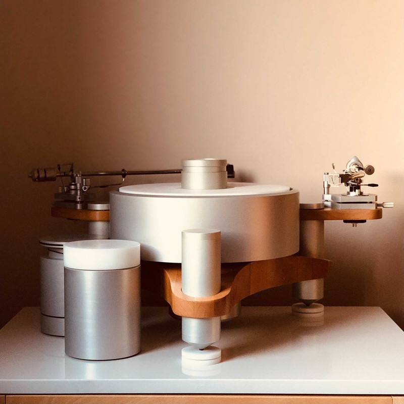
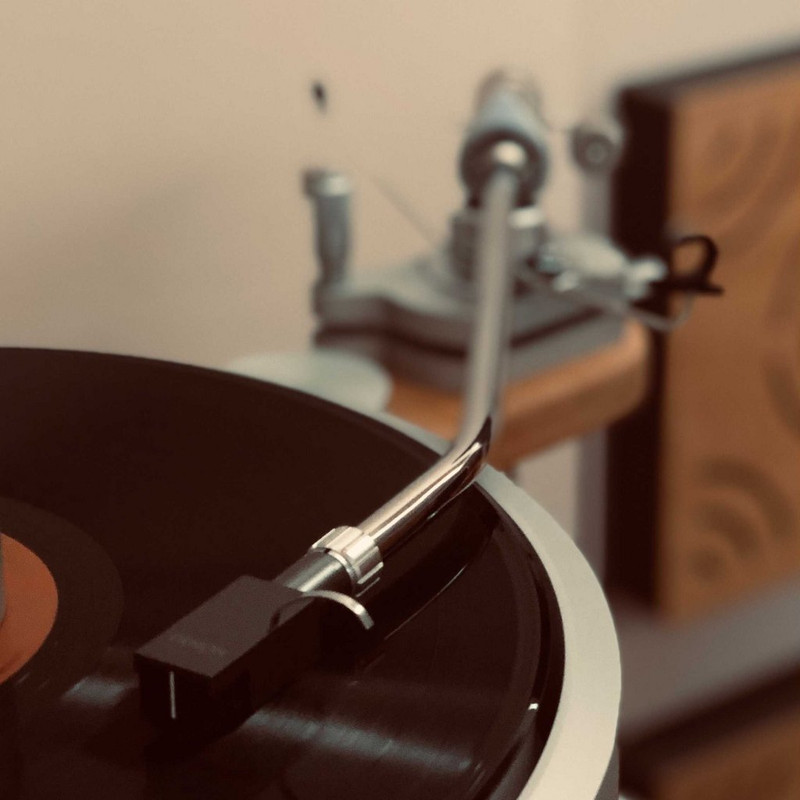
The turntable formally features the new platter "system".
Introduction
After a few years using the turntable with the original design structure, and definitely after the gradual update of key drive components, the last item I've been delaying is the new turntable platter "system". I say system instead of platter, as it consists of two separate platters that work as one via direct coupling. This is similar to the old platter system (high mass aluminium platter + low mass POM (*) platter + three point coupling utilizing ceramic balls).
(*) POM - polyoxymethylene, brand name Delrin, Hostaform, Kocetal.
Why change at all?
Most of the wishes from that list are quite possible now due to better material availability and a bit more machining experience, so let us turn our attention to the increase of rotational inertia. In line with flywheel principles, the rotational inertia of a cylinder, with little changes to mass, can be changed by direct redistribution of said mass. When the mass is moved towards the rim of the cylinder, and the radius of the cylinder is slightly increased, the results can be very interesting.
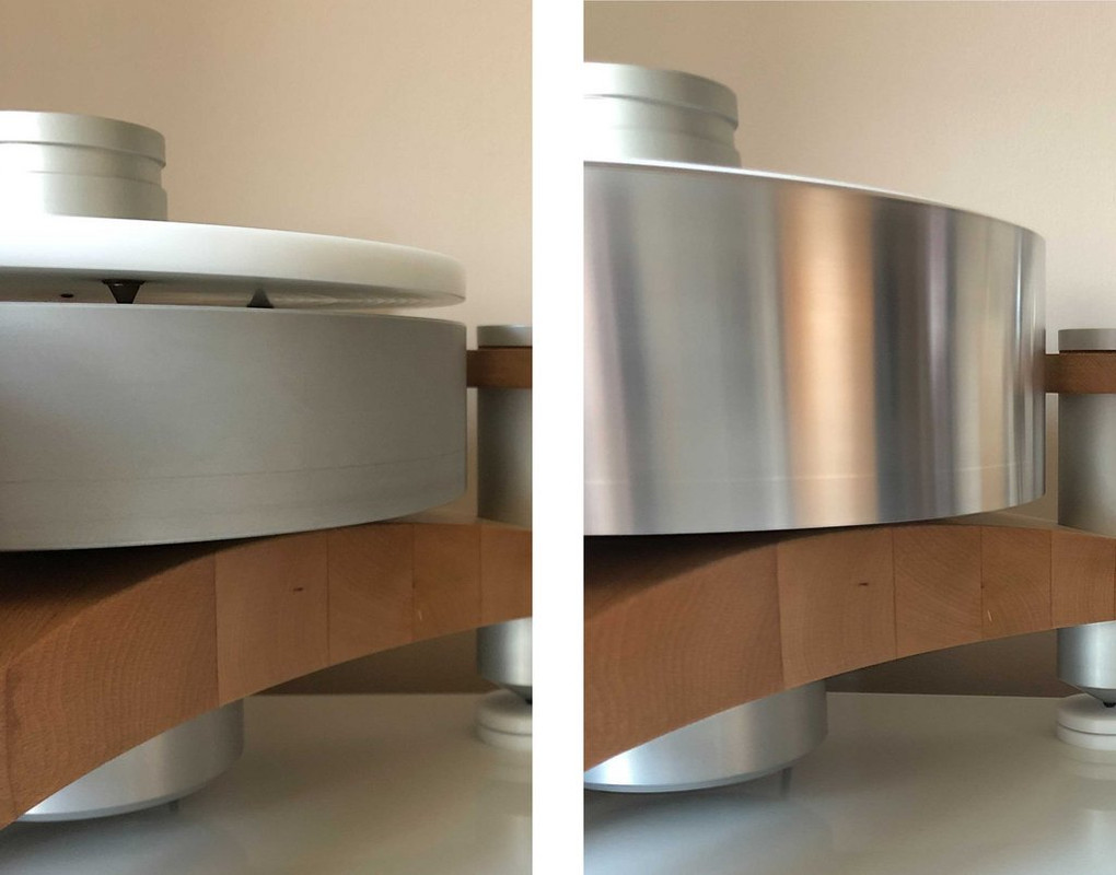
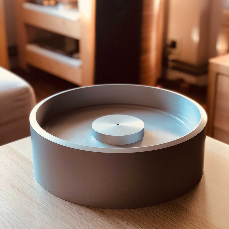
The new high mass platter has been machined out of a single piece of 6061 aluminium, dimensions 350mm х 350mm х 120mm.
Dimensions of the completed platter come to a diameter of 330mm and total height of 110mm. Most of the mass has been moved towards the edge of the platter, while the platter itself is mostly hollowed out in order to accommodate the POM platter. The bottom side of the platter has been gradually machined to help dissipate vibrations and mount the magnetic markers that help control the rotational speed.
The new low mass platter has been machined out of a single piece of POM (specifically Delrin), dimensions 310mm х 310mm х 60mm.
Dimensions of the completed platter come to a diameter of 296mm and total height of 50mm. Most of the mass has been moved towards the edge of the platter, while the platter itself is mostly hollowed out in order to accommodate the fit within the high mass platter. The bottom side of the platter has been gradually machined to help dissipate vibrations and mount the ceramic balls that help the POM platter rest on the high mass platter. POM is very difficult to glue, so the ceramic balls have been seated based on friction.
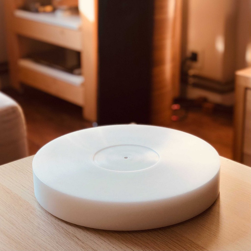
The two platters are coupled via three ceramic balls, Si3N4 Grade 5, with a diameter of 3mm. Such a coupling can get as close as possible to guarantee the least number of touching points. When the platters are joined together, a 5mm slit is visible along the inside edge of the high mass platter, while the low mass platter protrudes vertically by 2mm. At the same time, the POM platter being with a slightly smaller diameter than an LP, and the high mass platter being machined at a slight angle helps handle records more comfortably.
Results
Looking back at the wish list, I kind of feel I've acomplished what I set out for, but let's look at them individually.
Functionally, the results are quite expected. I feel that it aesthetically fits better with the rest of the turntable due to the changes of the other components, especially after the addition of the rim drive. The rotational mass is similar, thus presenting little additional challenge to the drive system, although it seems that rotational speed is more readily maintained now in relation to changes during reproduction (easy to ascertain from the logs of the computer drive system).
Sonically, I was taken aback a bit by the results. I knew I wanted to do this mostly for the visual element, so wasn't counting too much on sonic changes. However, it seems that this change has made the largest stride forward out of all the structural changes I've done so far. The total noise level of the system is very noticeably reduced - to the point that during a few records, I checked cartridge settings on the Devialet more than a couple times. There is an ease and fluidity to the reproduction, almost a direct and very stark contrast to the brutality of a 20kg rotational element.
Back to listening - I'd say that is enough structural changes for quite a bit now.
Introduction
After a few years using the turntable with the original design structure, and definitely after the gradual update of key drive components, the last item I've been delaying is the new turntable platter "system". I say system instead of platter, as it consists of two separate platters that work as one via direct coupling. This is similar to the old platter system (high mass aluminium platter + low mass POM (*) platter + three point coupling utilizing ceramic balls).
(*) POM - polyoxymethylene, brand name Delrin, Hostaform, Kocetal.
Why change at all?
- The old platter system was a compromise between availability of materials (raw sizes), and the lack of advanced machining experience;
- The open concept of the old system allowed for a potentially negative vibratory influence;
- The individual POM platter, due to it being quite thin, is subject to changes due to temperature and humidity fluctuations which may lead to eventual concentricity issues (runout).
- The new aluminium platter should encompass the POM platter within an internal cavity, to protect it, and the record from potential parasitic vibrations and partial temperature variations;
- The new POM platter should be thicker in order to increase rigidity and thermal stability;
- Total system mass should be similar to the current one in order to retain drive calibration;
- Total rotational inertia should be increased, hopefully by at least twice;
- Further machining precision with a runout at, or about, 0.01mm.
Most of the wishes from that list are quite possible now due to better material availability and a bit more machining experience, so let us turn our attention to the increase of rotational inertia. In line with flywheel principles, the rotational inertia of a cylinder, with little changes to mass, can be changed by direct redistribution of said mass. When the mass is moved towards the rim of the cylinder, and the radius of the cylinder is slightly increased, the results can be very interesting.
The new high mass platter has been machined out of a single piece of 6061 aluminium, dimensions 350mm х 350mm х 120mm.
Dimensions of the completed platter come to a diameter of 330mm and total height of 110mm. Most of the mass has been moved towards the edge of the platter, while the platter itself is mostly hollowed out in order to accommodate the POM platter. The bottom side of the platter has been gradually machined to help dissipate vibrations and mount the magnetic markers that help control the rotational speed.
The new low mass platter has been machined out of a single piece of POM (specifically Delrin), dimensions 310mm х 310mm х 60mm.
Dimensions of the completed platter come to a diameter of 296mm and total height of 50mm. Most of the mass has been moved towards the edge of the platter, while the platter itself is mostly hollowed out in order to accommodate the fit within the high mass platter. The bottom side of the platter has been gradually machined to help dissipate vibrations and mount the ceramic balls that help the POM platter rest on the high mass platter. POM is very difficult to glue, so the ceramic balls have been seated based on friction.
The two platters are coupled via three ceramic balls, Si3N4 Grade 5, with a diameter of 3mm. Such a coupling can get as close as possible to guarantee the least number of touching points. When the platters are joined together, a 5mm slit is visible along the inside edge of the high mass platter, while the low mass platter protrudes vertically by 2mm. At the same time, the POM platter being with a slightly smaller diameter than an LP, and the high mass platter being machined at a slight angle helps handle records more comfortably.
Results
Looking back at the wish list, I kind of feel I've acomplished what I set out for, but let's look at them individually.
- Encompass the low mass platter. The new aluminium platter is 40mm taller than the old one (an increase of 57%) and almost completely envelops the new POM platter. As intended, the new POM platter protrudes by about 2mm (only 4% of the total height visible). The diameter is now 330mm (an increase of 3%), bringing the total mass of the platter to 14.85kg (an increase of 2%).
- A more rigid low mass platter. The new POM platter is 35mm taller than the old one (an increase of 320% or more than three times). The diameter is 296mm (a decrease of 8%), bringing the total mass of the new low mass platter to 3.69kg (an increase of 217% or more than three times).
- Total system mass close to the current. The old system has a total mass of 17.15kg, as a result of the high mass platter (14.56kg), the low mass platter (1.69kg) and the bronze couplers (0.9kg). The new system has a total mass of 18.54kg, due to the bronze couplings being eliminated. The total system mass has been increased by 8%, which is within the limits of expectation.
- Increase rotational inertia by two times. The old system has uniform mass distribution, bringing the total rotational inertia for that system to 0.221 kg.m2. The new system has mass distributed near the edge of the platter in accordance to flywheel principles, bringing the total rotational inertia of the system to 0.485 kg.m2, an increase of 220% or 2.2 times.
- Further machining precision with ±0.01mm runout. I used a Mitutoyo dial indicator graduated to 0.005mm. The total runout of the system has resulted with negligible movements of the dial, which is almost on the level of surface dust - the deviation from concentricity within rotation on the turntable (horizontal and vertical) is less than 0.01mm.
Functionally, the results are quite expected. I feel that it aesthetically fits better with the rest of the turntable due to the changes of the other components, especially after the addition of the rim drive. The rotational mass is similar, thus presenting little additional challenge to the drive system, although it seems that rotational speed is more readily maintained now in relation to changes during reproduction (easy to ascertain from the logs of the computer drive system).
Sonically, I was taken aback a bit by the results. I knew I wanted to do this mostly for the visual element, so wasn't counting too much on sonic changes. However, it seems that this change has made the largest stride forward out of all the structural changes I've done so far. The total noise level of the system is very noticeably reduced - to the point that during a few records, I checked cartridge settings on the Devialet more than a couple times. There is an ease and fluidity to the reproduction, almost a direct and very stark contrast to the brutality of a 20kg rotational element.
Back to listening - I'd say that is enough structural changes for quite a bit now.
Mike Hanson
Trying to understand...
Stunning!
Darren L
Egalitarian
Excellent work, that's quite an accomplishment to achieve, it looks fantastic IMHO and I would love to hear it , from the pics and description it has the certainly has the finish and the build to compete with many of the high end Turntables on the market, you should be justifiably very proud of your work @InSides well done sir!
Darren L
Egalitarian
Well if you are ever in my neck of the woods (Veles, Macedonia) you are more than welcome to hear it.
Thanks , that's a very kind offer
Tony L
Administrator
@InSides Any further subjective feelings of the contrast between belt and rim-drive? Given the no-compromise approach I’d actually be fairly tempted to add another motor VPI-style and double the torque!
The two-part platter is really neat, a truly beautiful execution of the concept. I’ve long suspected one reason EMTs and 124s are so successful is the light platter on top of a pretty massive sub-platter. I guess one could argue Nottingham Analogue do something similar with the carbon top-platter on the Hyperspace and above. Breaking the structure makes a lot of sense to me and seems to get some way to a ‘best of both worlds’ where you get the absolute rock-solid pitch of a high-mass approach, but retain the life and vitality of lower-mass turntables. I’m curious as to whether your thinking aligns with this or whether you arrived here from a different trajectory.
PS Astonishing work, fit and finish, it really does look as good as anything on the market at any price.
InSides
dŵr
Thanks all, very humbled by your comments.
@Tony L, let me try to address your notes separately.
Multiple Motors
When I started looking into designing a turntable, after owning a number of (albeit all belt-driven) turntables, I decided that whatever the approach, a high torque motor would be used. The thinking behind this was that if I decide to change the concept I could have some leeway. So I ordered a number of high torque BLDC motors, and originally built multiple motor pods (at one point I had three motors driving the platter at the same time). That approach brought a level of complication on the drive electronics as the motors are rarely matched and suffer from varying torque curves.
There are many examples I've seen. One very interesting to me is the Audionote TT3 which, according to Audionote, uses three high torque motors and a very light platter. Another approach, that I don't really like based on photos only, is the Acoustic Signature Invictus with its six motors - I don't understand why six of them but I reserve the right it may serve a proper purpose. Then there is Kuzma, who is notable by the fact that, for his reference turntable, went from two motors, to four motors, then to one motor. He justified the changes as going from AC to DC motors, but I've always felt (although unconfirmed) that such an approach is to simply provide an upgrade path for those willing to do so.
But with testing and several years of operation, I've concluded that adding up on motors (these BLDC motors) actually yields much less benefit than the added complication of the drive electronics. As long as the single motor is competent, of course.
Split Platter Design
My initial driving idea was to figure out a way for the bearing spindle to have as close to nonexistent contact with the playing surface. Typically bearing spindles extend to the actual record spindle, but I felt that one way to minimize bearing noise is to eliminate that contact surface. One could make a fully magnetic bearing, but I shied away from that approach since I feel that mechanical grounding needs to exist, and wanted to avoid spring-like behavior from magnets. That of course required quite a massive bearing, which I've elaborated on earlier.
So I drew up the original split platter where the bearing spindle makes contact only with the lower (high mass) platter, and the record surface makes contact with only a "mat-like" surface that rests on the lower platter.
Now, there are inherent complications to that approach. One cannot make the top platter as thin as I wanted (mat like) since it would have little to no rigidity. So I went with a minimum thickness of 15mm initially and the next item was coupling - I wanted to have as little contact as possible to avoid vibration/noise creep-up. Settled on a tri-point support, and used high grade ceramic balls due to both their load bearing capacity as well as the very high level of sphericity guaranteeing as little as possible contact.
I did a few experiments with only a high mass platter. Quickly dropped them as, while I clearly saw the advantage that huge rotational inertia brings to the game, I also felt that music was, for the lack of better words, sucked out as if overdamped. Adding mats and or other paraphernalia yields it moot from a simplicity perspective and I'd rather not bring solutions to problems that I could easily avoid by updating the concept. Which brings us again to where we are.
Material wise, aluminium was a clear choice for the high mass platter as it is machinable, available, and non-magnetic. I did think of bronze at one time, but I failed to see the advantage of adding close to three times more mass to the platter, not to mention the prohibitive material cost (the bronze blank required alone would be in excess of £1K).
For the top platter, I wanted to experiment with PVC as I felt it would be as close to actual records as possible, especially from a vibratory standpoint. I quickly learned why people do not use it (it destroys tools when machining, absorbs cutting liquids and very much releases chlorine). I tested all the various popular alternatives - glass was a no go, acrylic was just dead sounding (but it is cheap and easy to machine so I guess I understand why so many turntable platters are made of it), even whipped out a PTFE sheet, but ultimately settled on POM as it was as close to PVC as possible, while proving to be a joy to machine and remain stable. And it is also light (only 2% more dense than PVC).
Tony L
Administrator
But with testing and several years of operation, I've concluded that adding up on motors (these BLDC motors) actually yields much less benefit than the added complication of the drive electronics. As long as the single motor is competent, of course.
I suspect you are right. I can see the benefit of it with low-mass suspended decks like the Voyd where it negates a sideways force on the suspended element, but if you have sufficiently high torque as is then job done.
So I drew up the original split platter where the bearing spindle makes contact only with the lower (high mass) platter, and the record surface makes contact with only a "mat-like" surface that rests on the lower platter.
For that aspect the Roksan idea of a detachable centre spindle that is removed once the record is centred makes a lot of sense. I’m not a huge fan as, other than being awkward, I believe there is an advantage to be had with a path from the record to mains earth so static charge has a path other than via the cantilever/cartridge/arm. For years now I have made sure my centre spindle gets a beep from a multimeter!
I did a few experiments with only a high mass platter. Quickly dropped them as, while I clearly saw the advantage that huge rotational inertia brings to the game, I also felt that music was, for the lack of better words, sucked out as if overdamped.
That is certainly my findings after owning a fairly large and diverse range of record decks over the years. Go too light and you lose scale and slam, go too heavy/damped and you kill the meaning/intent of the music.
Basically I’ve ended up sacrificing noise. I accept I will never get anything approaching Verdier or SP1000 levels of silence out of a vintage idler deck, but I can get the rest to my satisfaction. I can live with that!
InSides
dŵr
For that aspect the Roksan idea of a detachable centre spindle that is removed once the record is centred makes a lot of sense. I’m not a huge fan as, other than being awkward, I believe there is an advantage to be had with a path from the record to mains earth so static charge has a path other than via the cantilever/cartridge/arm. For years now I have made sure my centre spindle gets a beep from a multimeter!
You've actually hit the nail on the head with both awkwardness and grounding. One of the biggest machining issues for the top (low mass) platter has always been ensuring that the threaded hole for the record spindle is absolutely on axis. I have had multiple situations with prototypes where although the machining was spot on, the runout of the threaded hole (typically M6) is significant enough to produce both visible wobble and introduce an element of wow during playback. Almost no other manufacturer/designer has that kind of issue as the bearing axis is guiding the record rotation with the platter providing horizontal support only.
Grounding is also another issue I've dealt with especially with a detachable record spindle. In my case, it may cause issues of concern with the Arduino boards driving the drive controller logic - a non-controlled static discharge can effectively freeze the Arduino so requiring a hard reset. Have not had any occurrences lately though - but I designed a conductive "brush" that can mount on the underside of the spindle to provide for a ground path while avoiding a firmer contact.
Basically I’ve ended up sacrificing noise. I accept I will never get anything approaching Verdier or SP1000 levels of silence out of a vintage idler deck, but I can get the rest to my satisfaction. I can live with that!
There is a lot to be said about idlers as well as the way in which we perceive music. I am guided by numbers, but I prefer the emotional investment and "what feels right", even with this design. If one goes back earlier in the thread, I have shown that the belt drive (via the flywheel) is measurably lower in noise than the rim drive.
But I still use the rim drive exclusively.
Last edited:
InSides
dŵr
With the following update, I kind of have to go against my own advise from earlier "I'd rather not bring solutions to problems that I could easily avoid by updating the concept".
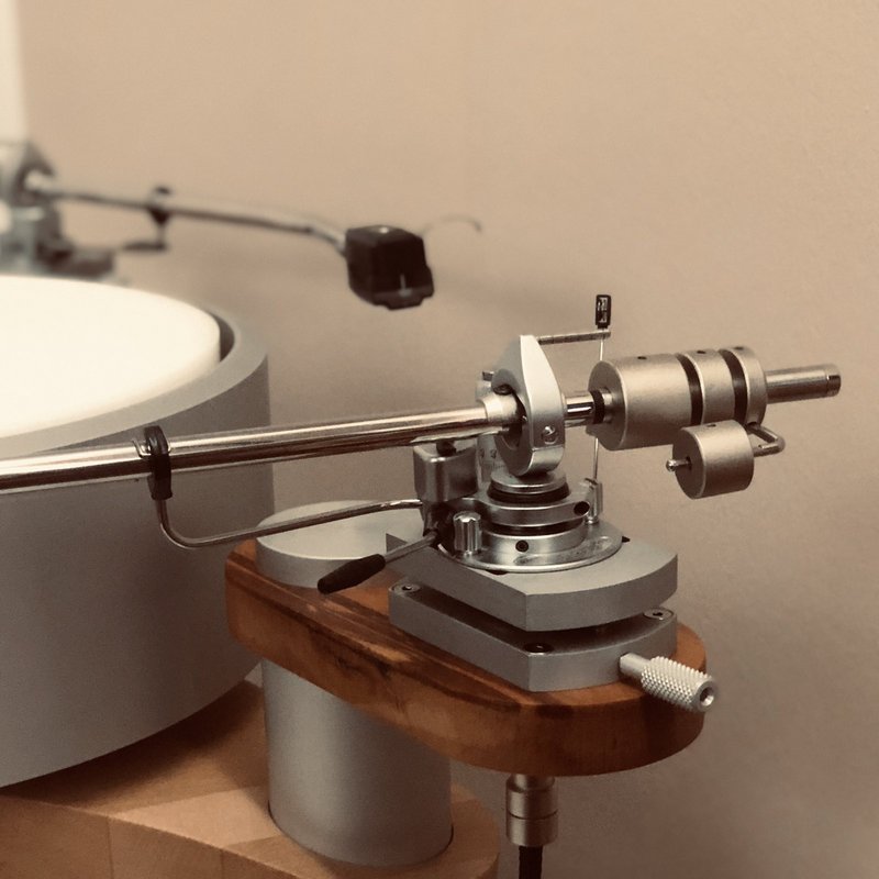
When updating the platter system, I went for a higher platter. This automatically meant that the tonearms need to be raised by at least 15mm for comfortable use and proper orientation. To do so, I could do one of the following:
Since I use tonearms with removable headshells, and I have multiple headshell/cartridge combinations, I've found that the nominal vertical distance between the top of the tonearm tube and the stylus tip varies, sometimes by as much as 3mm. Every time I swap a combo, I need to modify the height of the tonearm. Everyone who's ever used a SME 30xx tonearm has probably at one time or another cursed the "grub screw locking the tonearm collar" solution to that problem. It is complicated, difficult to reach and often imprecise.
If only there were a solution that would provide (1) easy to reach, (2) repeatable and (3) precise setting of the tonearm height. Many tonearms now feature that capability by design. Even my own design, featured earlier in this topic, has provisions for VTA on-the-fly, using a custom bronze screw. But the SME is not my design, and I'd rather not modify any of its parts. I've long been fascinated with Jeff Spall's (Audiomods) use of a readily-available micrometer head, but his approach was also custom to his tonearm. I researched other readily available options which did work on a SME sliding base, but alas, still required some modification of the SME tonearm (namely removing the screening can and figuring out a way to reattach the tonearm cable). This was a magnificent ready-made device, beautifully executed and I would have loved to just mount it, but for the aforementioned reasons I had to look another way.
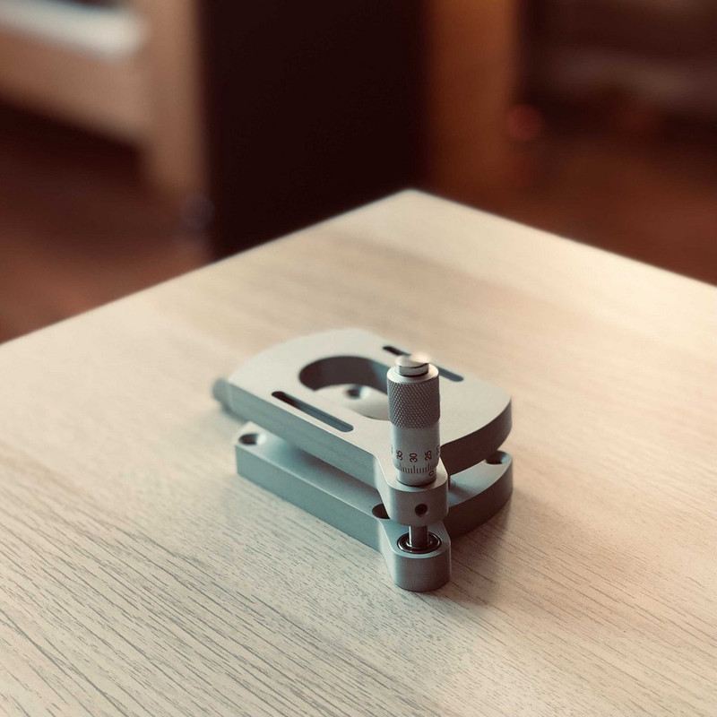
So I did this.
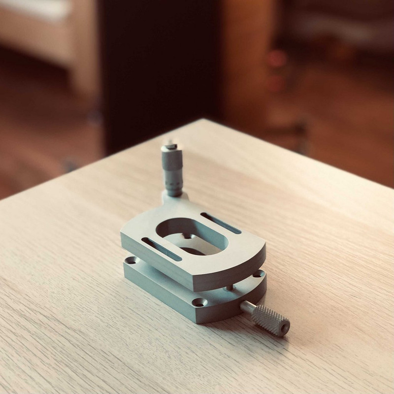
And from the back:
It is a precise mechanism for changing tonearm height for tonearms with an SME cutout (yes, that is as mouthful of a name as can be). It allows me to (1) easily, (2) precisely and (3) repeatedly change the tonearm height within a range of 12mm (*) while retaining the ability to (1) use the sliding base to set overhang, (2) retain the screening can and (3) perform no modifications to the tonearm at all.
(*) Well, up to 15mm but you'd have to sacrifice rigidity.
Here is an exploded view:
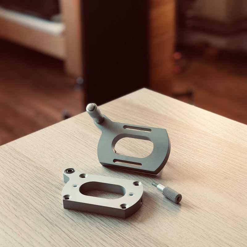
The tonearm is mounted to the top plate which features the slots that define the sliding base. Naturally this means that the standard SME sliding base is eliminated. The bottom plate features countersunk holes for the use of multiple types of screws to fasten to an armboard (I use machine screws as my armboards feature bronze inserts), two PTFE bushings for the guiding pins that stabilize the movement of the tonearm (SME 3012 is quite heavy) and a captive rolling bearing, mounted within a POM cap that facilitates the operation of the micrometer head.
The micrometer head is a cheap affair - I was quоted £150 for a Mitutoyo one and I promptly said my thanks and hung up the phone so that the sales rep does not hear me bursting into uncontrollable laughter. Luckily, this cheap one does the job just fine.
The mechanism is made out of 6082 aluminium for the plates and the locking screw, PTFE for the gliding bushings, POM for the bearing cap and bronze for the guiding pins. The finish is clear anodized, and while not as nice as I'd like it to be, should work just fine. The bearing is a standard 5x11x5 rolling bearing, and a micrometer head with a 9.5mm mounting collar.
It works much better that I had expected, and checks the boxes it needed for me (ease of use, repeatability, precision) while retaining mounting rigidity. One disadvantage of it, outside of the system it is currently being used, is a minimum base plate height of 20mm. That works wonderfully for me though.
Here it is in-situ:
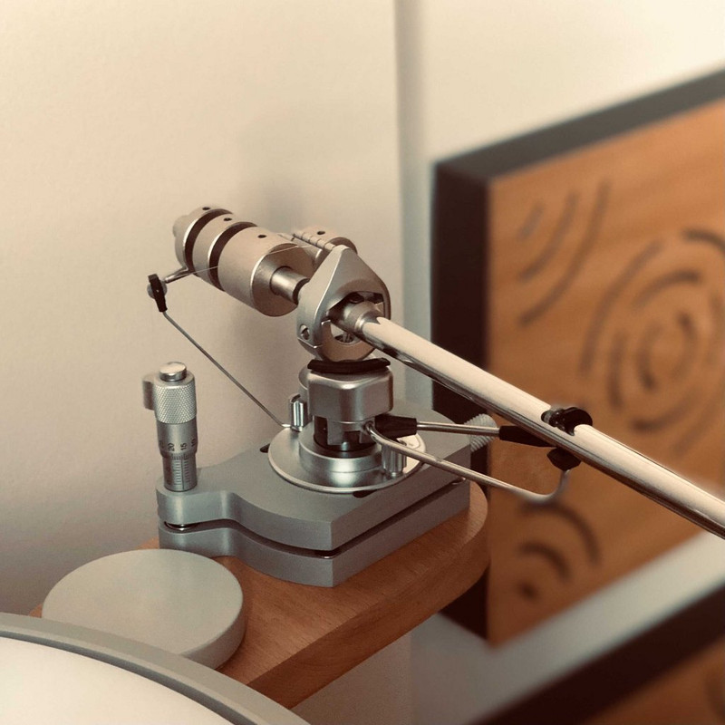
And here is it in operation in an attempted "art shot":
When updating the platter system, I went for a higher platter. This automatically meant that the tonearms need to be raised by at least 15mm for comfortable use and proper orientation. To do so, I could do one of the following:
- Completely remanufacture the tonearm pillars (huge effort which may ruin the aesthetics of the turntable); or,
- Design and machine a higher (20mm) base plate for the SME tonearms.
Since I use tonearms with removable headshells, and I have multiple headshell/cartridge combinations, I've found that the nominal vertical distance between the top of the tonearm tube and the stylus tip varies, sometimes by as much as 3mm. Every time I swap a combo, I need to modify the height of the tonearm. Everyone who's ever used a SME 30xx tonearm has probably at one time or another cursed the "grub screw locking the tonearm collar" solution to that problem. It is complicated, difficult to reach and often imprecise.
If only there were a solution that would provide (1) easy to reach, (2) repeatable and (3) precise setting of the tonearm height. Many tonearms now feature that capability by design. Even my own design, featured earlier in this topic, has provisions for VTA on-the-fly, using a custom bronze screw. But the SME is not my design, and I'd rather not modify any of its parts. I've long been fascinated with Jeff Spall's (Audiomods) use of a readily-available micrometer head, but his approach was also custom to his tonearm. I researched other readily available options which did work on a SME sliding base, but alas, still required some modification of the SME tonearm (namely removing the screening can and figuring out a way to reattach the tonearm cable). This was a magnificent ready-made device, beautifully executed and I would have loved to just mount it, but for the aforementioned reasons I had to look another way.
So I did this.
And from the back:
It is a precise mechanism for changing tonearm height for tonearms with an SME cutout (yes, that is as mouthful of a name as can be). It allows me to (1) easily, (2) precisely and (3) repeatedly change the tonearm height within a range of 12mm (*) while retaining the ability to (1) use the sliding base to set overhang, (2) retain the screening can and (3) perform no modifications to the tonearm at all.
(*) Well, up to 15mm but you'd have to sacrifice rigidity.
Here is an exploded view:
The tonearm is mounted to the top plate which features the slots that define the sliding base. Naturally this means that the standard SME sliding base is eliminated. The bottom plate features countersunk holes for the use of multiple types of screws to fasten to an armboard (I use machine screws as my armboards feature bronze inserts), two PTFE bushings for the guiding pins that stabilize the movement of the tonearm (SME 3012 is quite heavy) and a captive rolling bearing, mounted within a POM cap that facilitates the operation of the micrometer head.
The micrometer head is a cheap affair - I was quоted £150 for a Mitutoyo one and I promptly said my thanks and hung up the phone so that the sales rep does not hear me bursting into uncontrollable laughter. Luckily, this cheap one does the job just fine.
The mechanism is made out of 6082 aluminium for the plates and the locking screw, PTFE for the gliding bushings, POM for the bearing cap and bronze for the guiding pins. The finish is clear anodized, and while not as nice as I'd like it to be, should work just fine. The bearing is a standard 5x11x5 rolling bearing, and a micrometer head with a 9.5mm mounting collar.
It works much better that I had expected, and checks the boxes it needed for me (ease of use, repeatability, precision) while retaining mounting rigidity. One disadvantage of it, outside of the system it is currently being used, is a minimum base plate height of 20mm. That works wonderfully for me though.
Here it is in-situ:
And here is it in operation in an attempted "art shot":
a.palfreyman
pfm Member
You mentioned about the wobbly spindle:
An idea I'd considered for records with an off-set hole was to make a circular recess in the platter at say 1mm off-centre and then use an insert that fits the recess where the insert has a spindle that is also 1mm off-set, a bit like a cam. You can then rotate the insert so that you can off-set the centre spindle from 0 to 2mm. You could put a Vernier scale between the platter and the insert so as to indicate how much off-set has been applied. You would of course need to align the record so that you are removing off-set, not contributing to it! Just a thought...I have had multiple situations with prototypes where although the machining was spot on, the runout of the threaded hole (typically M6) is significant enough to produce both visible wobble and introduce an element of wow during playback
InSides
dŵr
Next is a small change that I had been avoiding for months - new wooden armboards. Reason for the change is a potential sagging issue due to the direction of the wood grain followed when the original ones were cut.
All three armboards with an SME cutout:
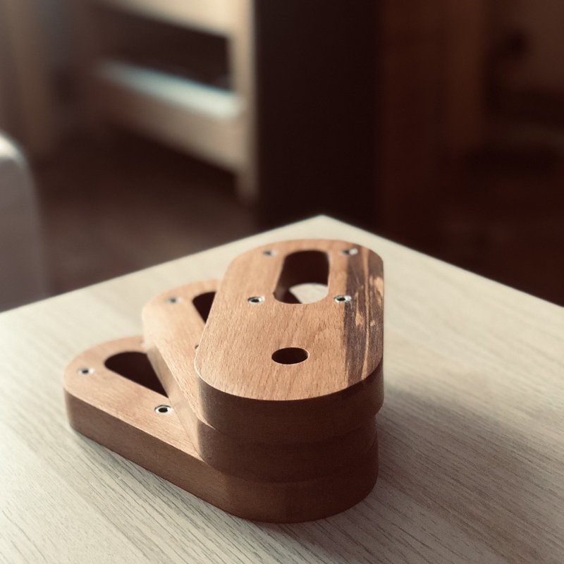
Cut out of a birch + pearwood laminate, finished with linseed oil and natural beeswax (I forgot how much effort waxing with natural beeswax is). For security, used machine screw inserts for tonearm mounting.
Already mounted:
I have yet to mount "something" on the third armboard.
All three armboards with an SME cutout:
Cut out of a birch + pearwood laminate, finished with linseed oil and natural beeswax (I forgot how much effort waxing with natural beeswax is). For security, used machine screw inserts for tonearm mounting.
Already mounted:
I have yet to mount "something" on the third armboard.