
You are using an out of date browser. It may not display this or other websites correctly.
You should upgrade or use an alternative browser.
You should upgrade or use an alternative browser.
dŵr & Friends (how not to build a turntable).
- Thread starter InSides
- Start date
InSides
dŵr
Seems like quite a small mating surface from bearing shaft to platter, any pics of the underside of the lower platter?
By design.
You have the dimensions of the bearing spindle in a previous post.
What may not be clear there is that there is an additional 0.5mm deep relief on the top surface, with a 30mm diameter, meaning the platter makes contact on a ring surface, with a total surface of ~550mm2 instead of the full circle area of ~1,250mm2.
EDIT: No photos at this point - perhaps when I next dismantle the platter during bearing maintenance?
Last edited:
James
Lord of the Erg\o/s
My gob is well and truly smacked out of the room! That is amazing originality, design, execution and pure craftsmanship that is rarely seen outside commercial manufacture. I say this as someone who takes great pride in my own original loudspeaker designs, so super well done InSides. I wish I could machine metal, but alas my handicraft is limited to woodwork.
I shall continue to watch your TT adventures with awe.
I shall continue to watch your TT adventures with awe.
InSides
dŵr
My gob is well and truly smacked out of the room!
You are very kind.
")
I shall continue to watch your TT adventures with awe.
Today's update within the hour.
InSides
dŵr
I'm curious about the azimuth slide, how smooth is it and does it affect warp riding? Is it underside of the rod exactly at the main arm bearing pivot centre height, or does it track a line through stylus and main bearing pivot point height?
The top ridge of the sliding surface has a fillet radius of approximately 0.05mm, which is the top of the resolution of the available printer. The shape is progressive, and the radius changes slightly to provide for more drag near the inner grooves of the record.
The line it tracks is on a plane between the main bearing pivot point and the stylus tip, significantly closer to the bearing pivot.
InSides
dŵr
Step #2. Drive.
Before I get on with this, a moment of honesty to clear my consciousness. This improvement step has been driven by pure vanity. When I initially designed dŵr, I wanted to hide all moving pieces out of sight, wherever possible, so that the visual aspect of the device would focus on the rotation of the platter. I wanted then (and still do now) to cover the motor spindle and belt pulley, so that only the belt is visible, akin to some Micro Seiki models.
Alas, time and financial pressure to finish the turntable, as well as inability to do some machining methods, led me to a simpler pod design, where both the pulley and the mass balance, including screws are visible.
In order to see what I was working with, a snapshot of the old motor pod:
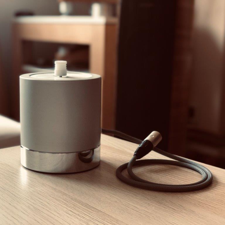
Machined in three separate components (not including the pulley) with three different materials. The pod itself is machined out of aluminium (6082), matt anodized. The mass balance is machined out of mild steel (4130), nickel and chrome plated, and the motor mount and the pulley machined out of polyoxymethylene (you see a pattern here ?).
Quiet, vibrationally stable, quite efficient. Not ugly by a longshot, I hope you will agree. Yet, the aesthetics had been gnawing at me.
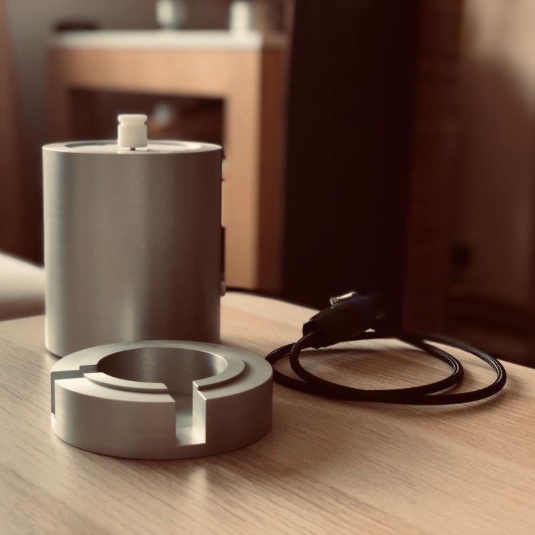
Breaking down, here is the new dŵr motor pod.
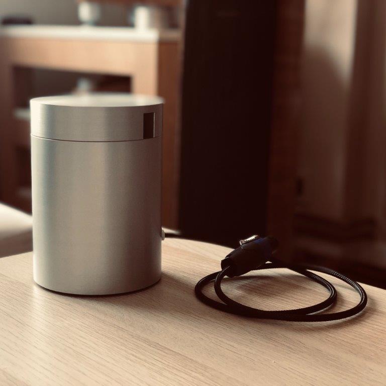
This latest monoblock approach comes in two components (apart from the pulley), and two different materials. The pod itself is machined out of aluminium (6082) with internally grooved adhesion fins for the motor to facilitate cooling, whereas the motor mount and the pulley are machined out of polyoxymethylene (POM).
The vanity element is an isolated aluminium cover which hides the pulley and belt contact, as well as all visible joints, matt anodized, and damped (*) with rubber foam and silicone drops.
(*) See below for issues with the cover.
This pod has the same outer diameter (120mm), with a slightly reduced internal diameter (by 22%) and an increased height (by 14%) yielding an increased total volume, and approximately the same overall mass as the older pod did with the steel mass balance included.
Power is courtesy of the same type of cable (Tasker C211), apart from the power connector now being a Neutrik SpeakOn NL4FC, taking the place of the earlier Neutrik XLR NC3MXX. I realise that a more appropriate connector set here would be the PowerCon series, yet I did not use it for the sole reason that the PowerCon series can only accomodate cables with a diameter larger than 8mm. I have justified the use of the SpeakOn here due to the fact none of my other equipment use SpeakOns.
Expectations
As mentioned earlier, this has been a pure vanity step. I would have been happy only with having aesthetics near what I wanted. That said, given the thought I put in this (and funds), I would say I expected at the very least (1) better motor cooling, (2) reduced belt slip, and (3) reduced overall noise.
Luckily, we can measure all this.
Results
Nothing to break in here - I started taking measurements approximately 30 minutes after the motor was installed. The cool down period was a bit longer due to the fact that I had to open up the electronics box to install the replacement Neutrik SpeakOn NL4MP.
Subjectively:
Temperature measurements were taken with the help of a laser, contactless thermometer:
And we really don't want that.
dŵr, by design, has an integrated compensator for these changes through the aforementioned algorithm, but if one can control external parameters, there would be less strain to the electronics, the motor will be relieved of quite a bit of fluctuations, which would in theory extend its lifetime.
With that out of the way, onwards to the truths that measurements yield.
1. Pulley
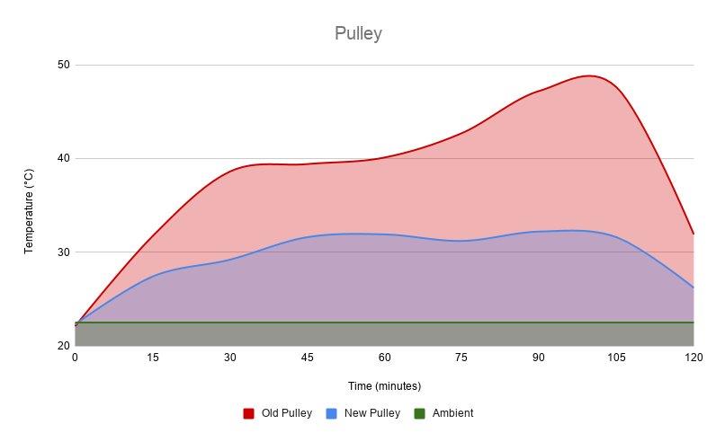
This location is important due to the direct contact of the pulley with both the motor spindle and the belt itself.
Difference are most easily discernable here and I daresay, drastic. A total drop in temperature for the pulley is evident across the spectar, and thermal management is more even. The average temperature drop is 8.6 degrees (°C), whereas the maximum observed difference is 15.4 degrees (°C).
2. Motor Mount
Also dubbed the cover in the graphs - I realised quite late in the game some confusion may be had with the actual vanity motor cover. To be clear, I mean the motor mount machined of POM here.
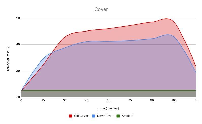
This location is important due to the full contact with the top surface of the motor.
Differences are smaller, but not insignificant, towards a better cooling solution. A total temperature drop is evident, although the temperature curves between the two solutions are quite complementary, both in their rise, and the expected plateau. The average temperature drop is 3.4 degrees (°C), whereas the maximum observed difference is 5.6 degrees (°C).
3. Pod
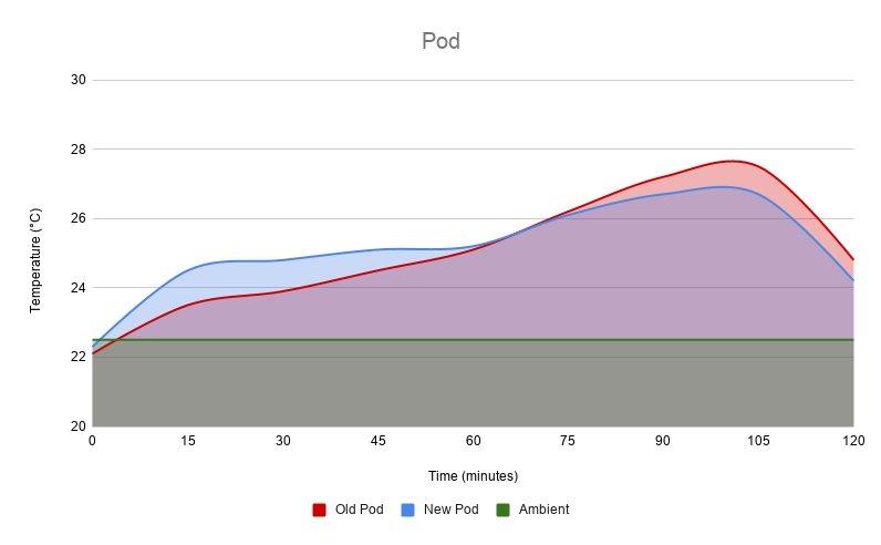
This location is important due to thermal management of the motor itself.
Differences are smallest here - quite minute due to the larger dissipation surface. Also important, the vertical axis is zoomed in to the area between 20 and 30 degrees (apart from the earlier 20 to 50 degrees) so that differences can be more easily observed. Crucial to note is that the plateau is reached earlier, and maintained on a lower position. The average temperature drop is 0.3 degrees (°C), whereas the maximum observed difference is 0.8 degrees (°C).
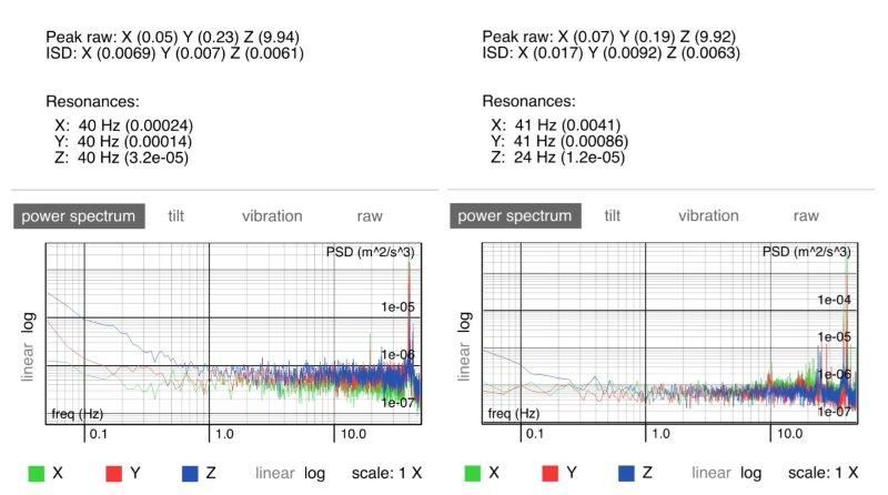
4. Vibrations
What follows is a display of vibrational measurements for a ~600 second (10 minute) rotation cycle (at 33 1/3 rpm), for the system with the old (left) and the new (right) drive pods (including different pulleys).
Z axis aligns with the central rotational axis for the turntable.
Onwards an upwards.
P.S. I had mentioned earlier that there were some issues with the vanity motor pod cover. Anyone who has ever cupped their hands to their ears to form a primitive horn can see how that would be an issue. The aluminium cover acted as a horn and amplified the pulley noise to the point of bother during quiet passages. Once I discerned where it came from, a few minutes of scissor work and a bit of rubber foam cured that ailment.
Before I get on with this, a moment of honesty to clear my consciousness. This improvement step has been driven by pure vanity. When I initially designed dŵr, I wanted to hide all moving pieces out of sight, wherever possible, so that the visual aspect of the device would focus on the rotation of the platter. I wanted then (and still do now) to cover the motor spindle and belt pulley, so that only the belt is visible, akin to some Micro Seiki models.
Alas, time and financial pressure to finish the turntable, as well as inability to do some machining methods, led me to a simpler pod design, where both the pulley and the mass balance, including screws are visible.
In order to see what I was working with, a snapshot of the old motor pod:
Machined in three separate components (not including the pulley) with three different materials. The pod itself is machined out of aluminium (6082), matt anodized. The mass balance is machined out of mild steel (4130), nickel and chrome plated, and the motor mount and the pulley machined out of polyoxymethylene (you see a pattern here
?).Quiet, vibrationally stable, quite efficient. Not ugly by a longshot, I hope you will agree. Yet, the aesthetics had been gnawing at me.
Breaking down, here is the new dŵr motor pod.
This latest monoblock approach comes in two components (apart from the pulley), and two different materials. The pod itself is machined out of aluminium (6082) with internally grooved adhesion fins for the motor to facilitate cooling, whereas the motor mount and the pulley are machined out of polyoxymethylene (POM).
The vanity element is an isolated aluminium cover which hides the pulley and belt contact, as well as all visible joints, matt anodized, and damped (*) with rubber foam and silicone drops.
(*) See below for issues with the cover.
This pod has the same outer diameter (120mm), with a slightly reduced internal diameter (by 22%) and an increased height (by 14%) yielding an increased total volume, and approximately the same overall mass as the older pod did with the steel mass balance included.
Power is courtesy of the same type of cable (Tasker C211), apart from the power connector now being a Neutrik SpeakOn NL4FC, taking the place of the earlier Neutrik XLR NC3MXX. I realise that a more appropriate connector set here would be the PowerCon series, yet I did not use it for the sole reason that the PowerCon series can only accomodate cables with a diameter larger than 8mm. I have justified the use of the SpeakOn here due to the fact none of my other equipment use SpeakOns.
Expectations
As mentioned earlier, this has been a pure vanity step. I would have been happy only with having aesthetics near what I wanted. That said, given the thought I put in this (and funds), I would say I expected at the very least (1) better motor cooling, (2) reduced belt slip, and (3) reduced overall noise.
Luckily, we can measure all this.
Results
Nothing to break in here - I started taking measurements approximately 30 minutes after the motor was installed. The cool down period was a bit longer due to the fact that I had to open up the electronics box to install the replacement Neutrik SpeakOn NL4MP.
Subjectively:
- The motor is quite cooler to the touch after working for a few hours;
- Belt slip has been reduced, which may also be due to the revised position of the belt on the platter (slightly higher up);
- Looks better to me (mission achieved!).
Temperature measurements were taken with the help of a laser, contactless thermometer:
- Measurements took place over a period of two hours (120 minutes) within 15 minute intervals;
- The motor was turned off for at least two hours prior to measurements;
- The latest working measurement is in the 105th minute, after which, the motor is turned off in order to establish cooldown performance in the last 15 minute interval;
- Three points of measurements are considered - (1) drive pod, (2) top motor mount and (3) pulley;
- Each individual measurement point, at every location is averaged between three individual measurements, in the hope to decrease (if not eliminate) the differential error present with the used measurement device;
- Ambient temperature held at steady 22.5 degrees Celsius, controlled via an OpenTherm enabled room thermostate.
And we really don't want that.
dŵr, by design, has an integrated compensator for these changes through the aforementioned algorithm, but if one can control external parameters, there would be less strain to the electronics, the motor will be relieved of quite a bit of fluctuations, which would in theory extend its lifetime.
With that out of the way, onwards to the truths that measurements yield.
1. Pulley
This location is important due to the direct contact of the pulley with both the motor spindle and the belt itself.
Difference are most easily discernable here and I daresay, drastic. A total drop in temperature for the pulley is evident across the spectar, and thermal management is more even. The average temperature drop is 8.6 degrees (°C), whereas the maximum observed difference is 15.4 degrees (°C).
2. Motor Mount
Also dubbed the cover in the graphs - I realised quite late in the game some confusion may be had with the actual vanity motor cover. To be clear, I mean the motor mount machined of POM here.
This location is important due to the full contact with the top surface of the motor.
Differences are smaller, but not insignificant, towards a better cooling solution. A total temperature drop is evident, although the temperature curves between the two solutions are quite complementary, both in their rise, and the expected plateau. The average temperature drop is 3.4 degrees (°C), whereas the maximum observed difference is 5.6 degrees (°C).
3. Pod
This location is important due to thermal management of the motor itself.
Differences are smallest here - quite minute due to the larger dissipation surface. Also important, the vertical axis is zoomed in to the area between 20 and 30 degrees (apart from the earlier 20 to 50 degrees) so that differences can be more easily observed. Crucial to note is that the plateau is reached earlier, and maintained on a lower position. The average temperature drop is 0.3 degrees (°C), whereas the maximum observed difference is 0.8 degrees (°C).
4. Vibrations
What follows is a display of vibrational measurements for a ~600 second (10 minute) rotation cycle (at 33 1/3 rpm), for the system with the old (left) and the new (right) drive pods (including different pulleys).
Z axis aligns with the central rotational axis for the turntable.
Onwards an upwards.
P.S. I had mentioned earlier that there were some issues with the vanity motor pod cover. Anyone who has ever cupped their hands to their ears to form a primitive horn can see how that would be an issue. The aluminium cover acted as a horn and amplified the pulley noise to the point of bother during quiet passages. Once I discerned where it came from, a few minutes of scissor work and a bit of rubber foam cured that ailment.
InSides
dŵr
Nice, I like the thinking on the azimuth and antiskate.
Yeah. When the lockdown started, did a whole treatise on antiskate which resulted in its own GitHub repository to house all the measurements and my conclusions. Not proud of the length though (25 pages) - seems I can rarely write short.
wylton
Naim and Mana member
When the lockdown started, did a whole treatise on antiskate ...
I think it's a subject that people rarely get to grips with; most people I guess are like me and set it to some medium value and forget about it. Of the arms I have here, the methods used are Falling weight (Naim Aro and Audiomods) and spring-applied (Zeta). The Aro has graduated nothched that relate to the tracking weight, but the Zeta and the Audiomods have no graduations at all, so it is left to the user to set the bias by ear.
MichaelC
pfm Member
The analysis of the steps to achieve the drive just goes to show much thought, attention and detail is required in the design and prototype stages of development. And people wonder why the end product in the shops cost so much after allowing for respective margins let alone the actual cost of build and an element to cover the design/prototype stages!
Awesome work InSides.
Awesome work InSides.
InSides
dŵr
I think it's a subject that people rarely get to grips with; most people I guess are like me and set it to some medium value and forget about it.
I rarely accept common truths without thought - especially if I have the ability to check it myself. Call it a character flaw - I've just found that through experimentation and research I learn more, and it stays (with me) longer.
My findings did confirm some popular understandings, so there is that. However, it allowed me to both (1) understand skating force so I can compensate for it, and (2) rely on a repeatable measurement method using instruments other than my ears.
If at any time you are bored beyond belief, you are welcome to read through those 25 pages. The GitHub repo where I've stored the research also has all of the data files recorded, FFT spectra, RAW materials, reports and methodology. I did it that way to allow for same data files to be processed by a different methodology in case my approach was/is flawed. Also shows how conclusions are based on actual available data and repeatable measurements.
The analysis of the steps to achieve the drive just goes to show much thought, attention and detail is required in the design and prototype stages of development. And people wonder why the end product in the shops cost so much after allowing for respective margins let alone the actual cost of build and an element to cover the design/prototype stages!
It helps that I design and build for myself, and not to a schedule nor to a price point. Pricing is always a difficult thing, and I am glad I do not answer to an audio company.
InSides
dŵr
Bonus update for today.
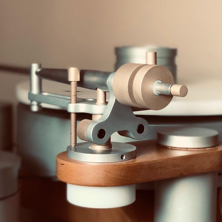
Once I went through the new finishing procedure (new to me) for the bearing, I couldn't help myself but think back to the original finishing for the tonearm parts (polished then lacquered). The lacquer was holding up nice, but due to sharp edges, it was prone to chipping.
So, I did what any sensible person (sensible in the sense of our hobby that is) would do, and I stripped the tonearm.
All bronze parts went for glass blasting and TiN (Titanium Nitride) plating via PVD (plasma vapor deposition).
Here it is after assembly and relocation (reason for relocation will make itself known in step #5 of our current plan).
sq225917
Bit of this, bit of that
Did Geoff swap the antiskate on the audiomods arm, the one I've seen pulls against a cam with a falling weight to give varied leverage across the record surface.
I'm surprised no test record exists with a fixed frequency tone across all of one side, this would allow easy measurement of the varying skating force to be derived from the change in channel balance and hence allow accurate antiskate mapping for the full arc.
I assume it's not a straight line variance, but actually follows the tracing distortion arc? And if so should be adjusted according to individual arm/cart geometry.
InSides
dŵr
I'm surprised no test record exists with a fixed frequency tone across all of one side
HFN002 comes close.
There are three tracks spread across the B side (outer, middle and inner grooves). It is not ideal (300Hz L+R at +15dB) but one can compensate for that.
InSides
dŵr
Step #3. Electronics.
Right smack in the middle of the plan / timeline, the modifications which caused me most dread. It required changes to the wooden elements for the electronics box, and is completely irreversible.
Prior to the modification, the electronics "box" contained (1) the DDS generator PCB, (2) the Class D multichannel amp PBC and (3) microcontroller "glue logic" PBC. All this powered by an external SMPS (15VDC/1A) through a Rean TinyXLR 4P connector.
And it worked quite fine, but I was missing three things (at least) - (1) elimination of an extra box (the SMPS was dangling behind the rack no matter its miniscule size), (2) a "master" switch to preserve OLED life and (3) easy access to the microcontroller programming interface to both implement new features and download worklogs.
To fit all this, we machined an additional level below the wooden frame, essentialy turning the box in a double decker. Lower deck now contains extra connectors and the SMPS, and the upper deck contains the electronics that were already in the frame.
It now looks like this:
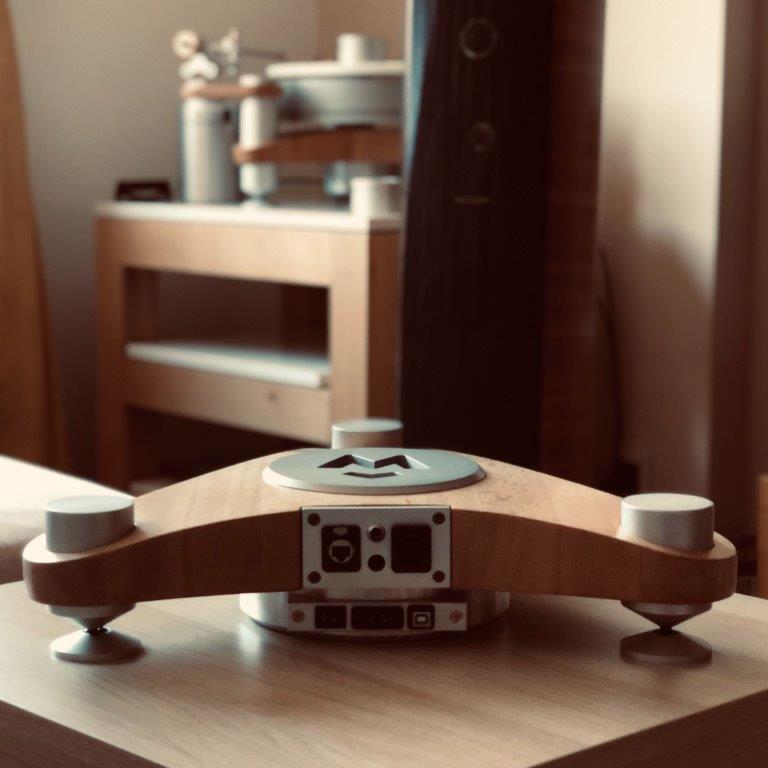
And given that connector details are not as visible as I'd like them to be for easier reference, here is another perspective.
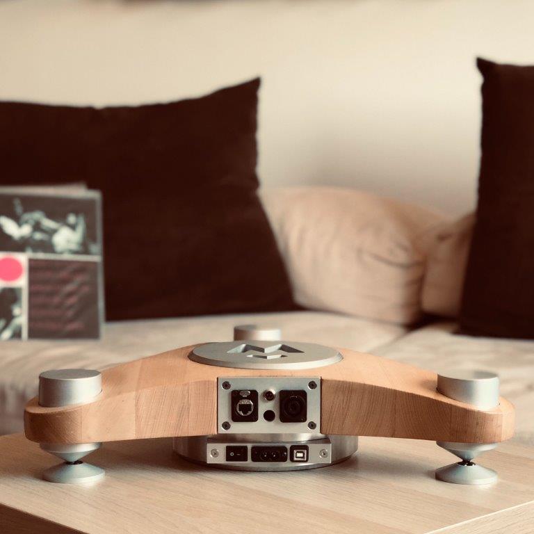
Upper deck connectors (upper left to lower right):
No measurements here. I am, however, very happy that I did not cause more harm than good.
Up next, microcontroller reprogramming.
(*) Future functionality is already in place. Still missing a proper plug - waiting on POM delivery.
Right smack in the middle of the plan / timeline, the modifications which caused me most dread. It required changes to the wooden elements for the electronics box, and is completely irreversible.
Prior to the modification, the electronics "box" contained (1) the DDS generator PCB, (2) the Class D multichannel amp PBC and (3) microcontroller "glue logic" PBC. All this powered by an external SMPS (15VDC/1A) through a Rean TinyXLR 4P connector.
And it worked quite fine, but I was missing three things (at least) - (1) elimination of an extra box (the SMPS was dangling behind the rack no matter its miniscule size), (2) a "master" switch to preserve OLED life and (3) easy access to the microcontroller programming interface to both implement new features and download worklogs.
To fit all this, we machined an additional level below the wooden frame, essentialy turning the box in a double decker. Lower deck now contains extra connectors and the SMPS, and the upper deck contains the electronics that were already in the frame.
It now looks like this:
And given that connector details are not as visible as I'd like them to be for easier reference, here is another perspective.
Upper deck connectors (upper left to lower right):
- Neutrik Ethercon to connect to the wired remote;
- Rean TinyXLR 3P to connect to the turntable platter sensor array;
- Empty space for future functionality (*); and
- Neutrik SpeakOn to connect to the motor.
- Master power switch;
- C8 power connector (mates to a AudioQuest NRG-Z2 power cable); and
- USB "B" connector to link to the Arduino Nano.
No measurements here. I am, however, very happy that I did not cause more harm than good.
Up next, microcontroller reprogramming.
(*) Future functionality is already in place. Still missing a proper plug - waiting on POM delivery.
InSides
dŵr
Step #4. Microcontroller.
I was supposed to replace the Arduino Nano with an Arduino Nano Every. Reason was/is increased memory capacity and better logging abilities to support advanced features.
And I wrote supposed since eventually, I was left with the original Arduino Nano. Nano Every is pin compatible, source code is complementary with the new controller, but there is a slight discrepancy in pin pullup requiremens which led to the fact that individual pins were not triggered rendering automatic speed control inoperative.
In practice, this meant that I would need to replace the 4 pullup resistors. But as this was done in the middle of a lockdown, I did the logical thing (again, logical to us in this hobby) and instead of replacing four resistors I refactored the entire code for increased efficiency and less resource strain.
Thus, the result of that is a new feature of the code, measurement of wow (nominal speed fluctuation) as an integral component of wow & flutter is now live. The feature is available in every code revision starting with the 02f96de commit. As earlier, all code portions available in the turntable's GitHub repository.
Expectations
When this thread started, I state that I did some indirect measurements which determined that W&F hovers around (or slightly below) 0.1%.
But what are relevant values? Researching around manufacturers specifications, especially modern ones, either yields no data, or data which has no context. So I went back and looked through the "NAB audio recording and reproducing standards for disk recording and reproducing", specifically the version from February 1964, which states the following:
How does that translate to actual products? Modern turntables often quote (where they do) values around or even worse than 0.1%, whereas vintage turntables (especially quartz controlled ones) often quoted 0.05% (Technics SL-Q2 quoted <0.012%).
As we are measuring speed fluctuations only, let us say I would be happy with values however smaller (better) than 0.1%.
Results
After 5 minutes of rotation at 33.(3) rpm, measured value is 0.006%.
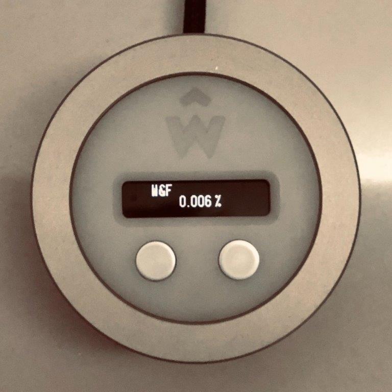
Better than expected by ~17 times (~17x).
After 5 minutes of rotation at 45.0 rpm, measured value is 0.005%.
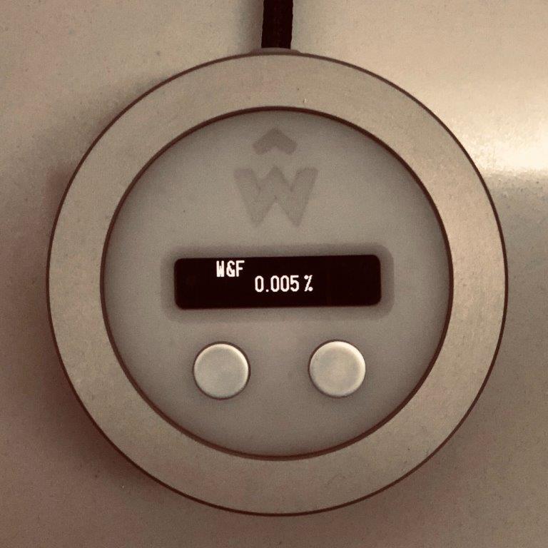
Better than expected by ~20 times (~20x).
As these are average values, and averages are influenced by extremes, we should see what the discrepancies are.
This is a polar plot of speed fluctuations for 40 full rotations, a total of 160 measured data points, for each nominal speed.
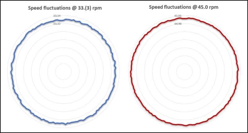
I am not sure I could do any better with this drive.
(**) And now we are getting back to the averaging. NAB folks were very clear in specifying the averaging approach. That is why, the implementation of this feature only takes into account the 16 last measurement points (4 full rotations). As such, it may vary at different times, but will show the closest values to W&F at the specific point at the record.
P.S. I like adhering to standards when they make sense. And this is where I should state that this drive does not adhere to point 1.25 of these standards "It shall be standard that the turntable platen shall attain its mean speed as defined in Section 1.05 in not more than 120 degrees rotation". With my turntable, it takes four complete rotations.
I was supposed to replace the Arduino Nano with an Arduino Nano Every. Reason was/is increased memory capacity and better logging abilities to support advanced features.
And I wrote supposed since eventually, I was left with the original Arduino Nano. Nano Every is pin compatible, source code is complementary with the new controller, but there is a slight discrepancy in pin pullup requiremens which led to the fact that individual pins were not triggered rendering automatic speed control inoperative.
In practice, this meant that I would need to replace the 4 pullup resistors. But as this was done in the middle of a lockdown, I did the logical thing (again, logical to us in this hobby) and instead of replacing four resistors I refactored the entire code for increased efficiency and less resource strain.
Thus, the result of that is a new feature of the code, measurement of wow (nominal speed fluctuation) as an integral component of wow & flutter is now live. The feature is available in every code revision starting with the 02f96de commit. As earlier, all code portions available in the turntable's GitHub repository.
Expectations
When this thread started, I state that I did some indirect measurements which determined that W&F hovers around (or slightly below) 0.1%.
But what are relevant values? Researching around manufacturers specifications, especially modern ones, either yields no data, or data which has no context. So I went back and looked through the "NAB audio recording and reproducing standards for disk recording and reproducing", specifically the version from February 1964, which states the following:
- 1.05 Turntable Speed (RPM) - It shall be standard that the mean speed of the recording turntable be either 33-95 or 45 RPM ± 0.1%, and the mean speed of the reproducing turntable be either 33-95 or 45 RPM ± 0.3%;
- 1.20 Wow and Flutter Factor (Reproducing) - It shall be standard that the average (*) deviation from the mean speed of the reproducing turntable when reproducing shall not exceed 0.1% of the mean speed.
How does that translate to actual products? Modern turntables often quote (where they do) values around or even worse than 0.1%, whereas vintage turntables (especially quartz controlled ones) often quoted 0.05% (Technics SL-Q2 quoted <0.012%).
As we are measuring speed fluctuations only, let us say I would be happy with values however smaller (better) than 0.1%.
Results
After 5 minutes of rotation at 33.(3) rpm, measured value is 0.006%.
Better than expected by ~17 times (~17x).
After 5 minutes of rotation at 45.0 rpm, measured value is 0.005%.
Better than expected by ~20 times (~20x).
As these are average values, and averages are influenced by extremes, we should see what the discrepancies are.
This is a polar plot of speed fluctuations for 40 full rotations, a total of 160 measured data points, for each nominal speed.
I am not sure I could do any better with this drive.
(**) And now we are getting back to the averaging. NAB folks were very clear in specifying the averaging approach. That is why, the implementation of this feature only takes into account the 16 last measurement points (4 full rotations). As such, it may vary at different times, but will show the closest values to W&F at the specific point at the record.
P.S. I like adhering to standards when they make sense. And this is where I should state that this drive does not adhere to point 1.25 of these standards "It shall be standard that the turntable platen shall attain its mean speed as defined in Section 1.05 in not more than 120 degrees rotation". With my turntable, it takes four complete rotations.