advertisement


Crimson 610/630s...

Dowser

Learning to bodge again..
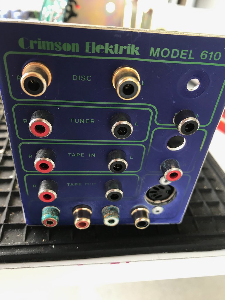
I've always wanted to try vintage Crimson gear, hence I paid way too much for a set of 610/630 monos recently (got a tax refund, didn't I :)).

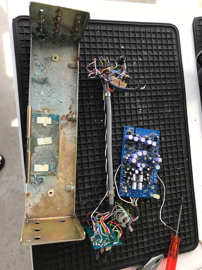
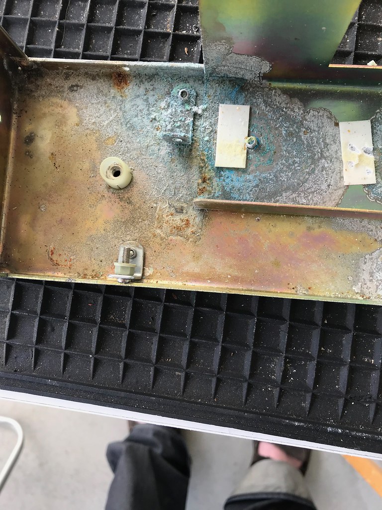
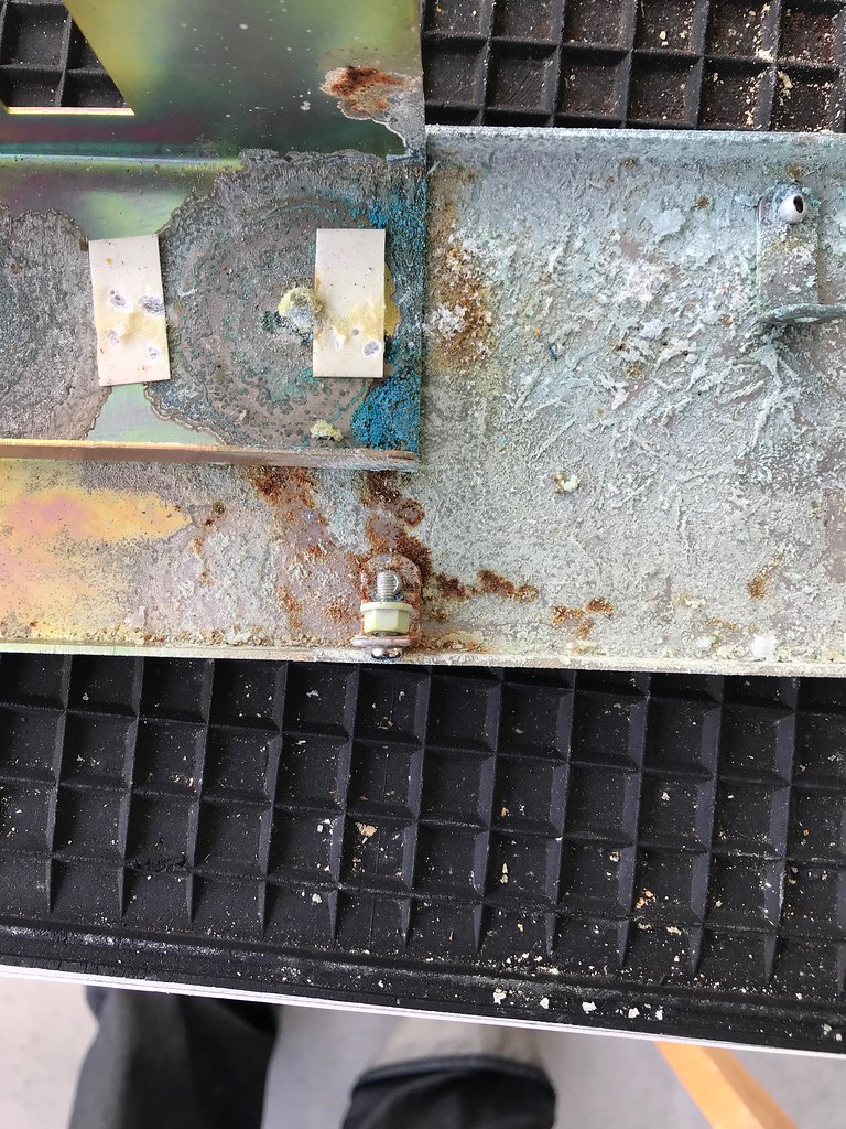
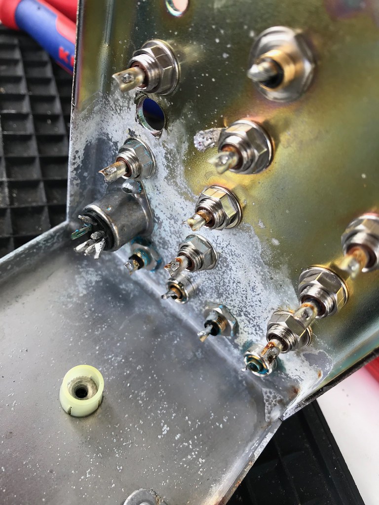
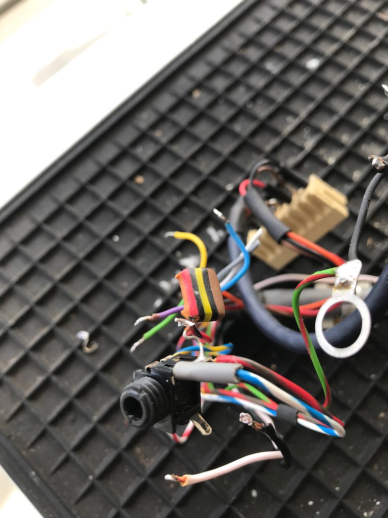
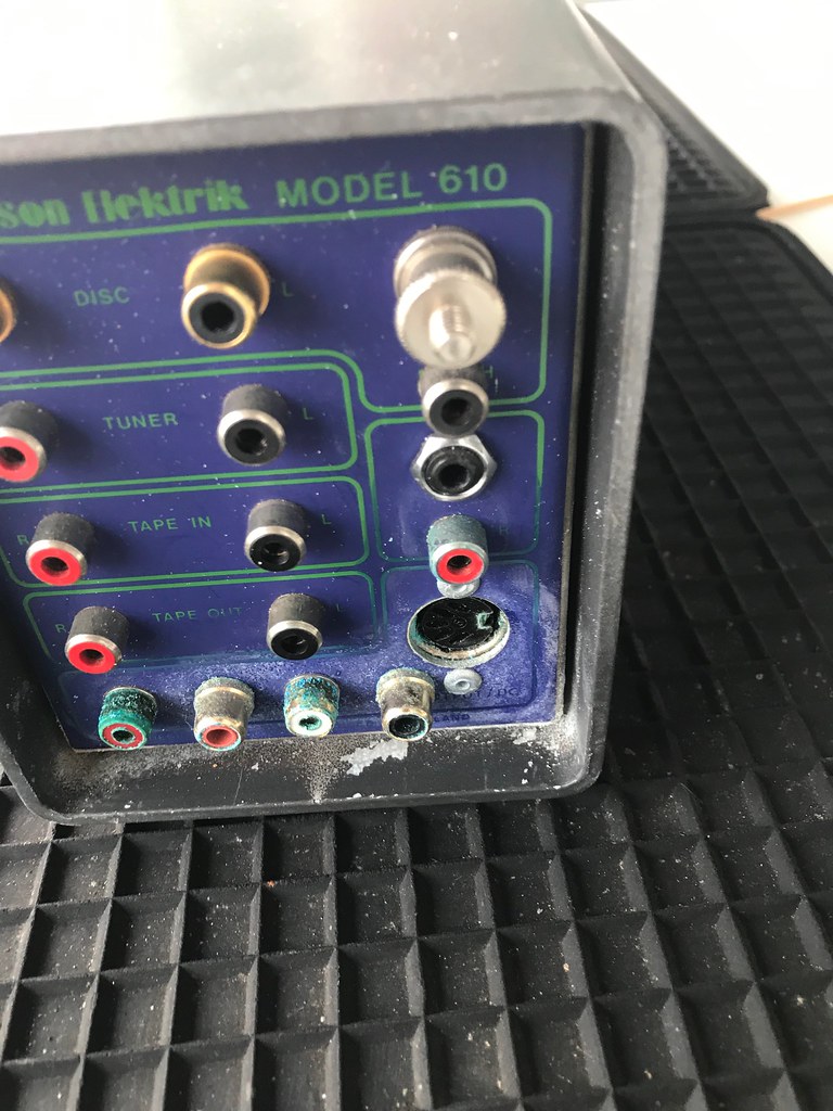
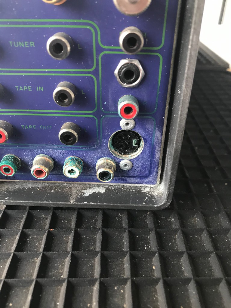
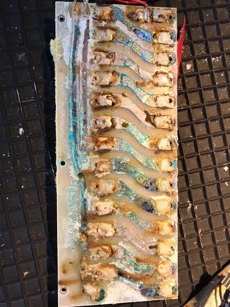
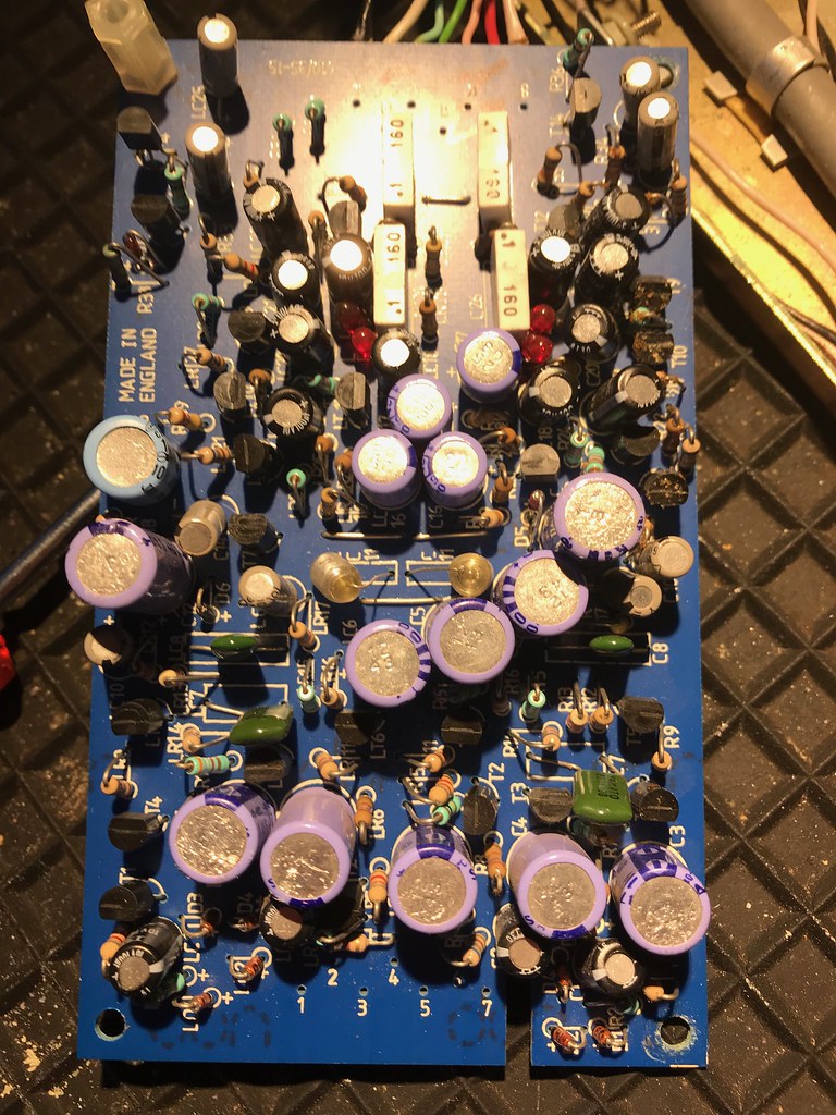
Here's a good reason not to store a late 80s battery powered pre-amp in your cellar for 10 years...

47707011331_10ee664450_b.jpg

33829617678_349b1d6a9b_b.jpg

47706928251_b003440182_b.jpg

46790779815_670fb5969f_b.jpg

47706928251_b003440182_b.jpg

46790779725_4627f2a718_b.jpg

47706925301_4512656f01_b.jpg

33829633448_c55f9e347d_b.jpg


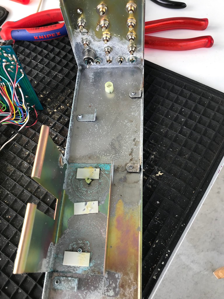
After a wash with fairy liquid
33829616818_e6d99bf7f7_b.jpg


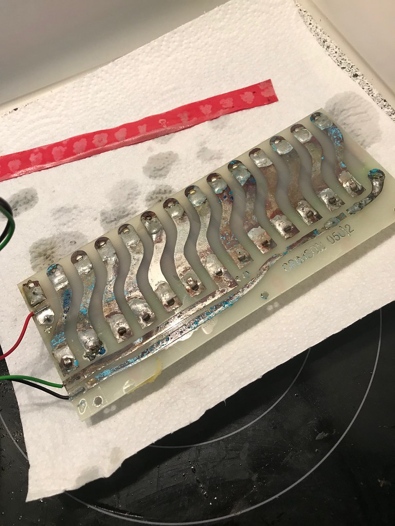
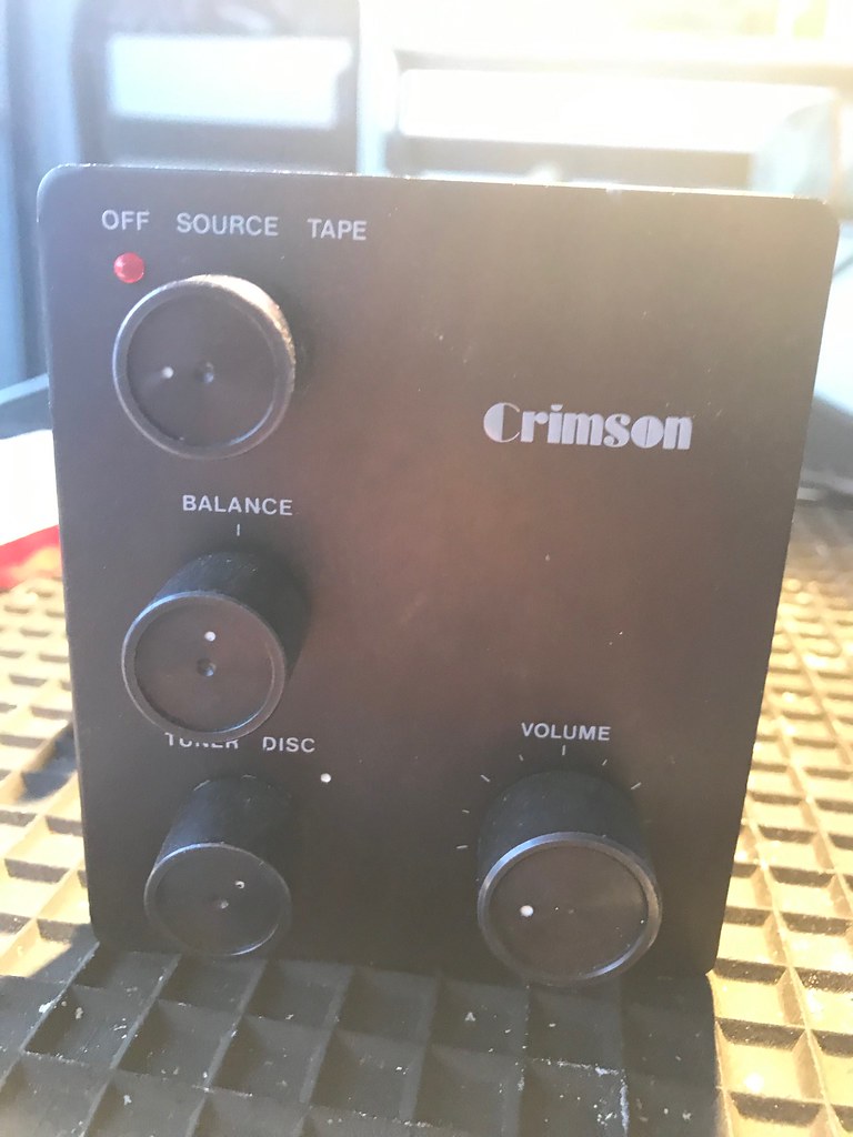
Love the classic look
40740561253_873951c10f_b.jpg


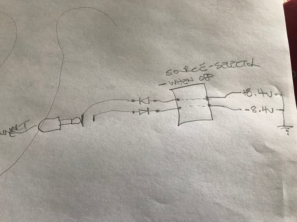
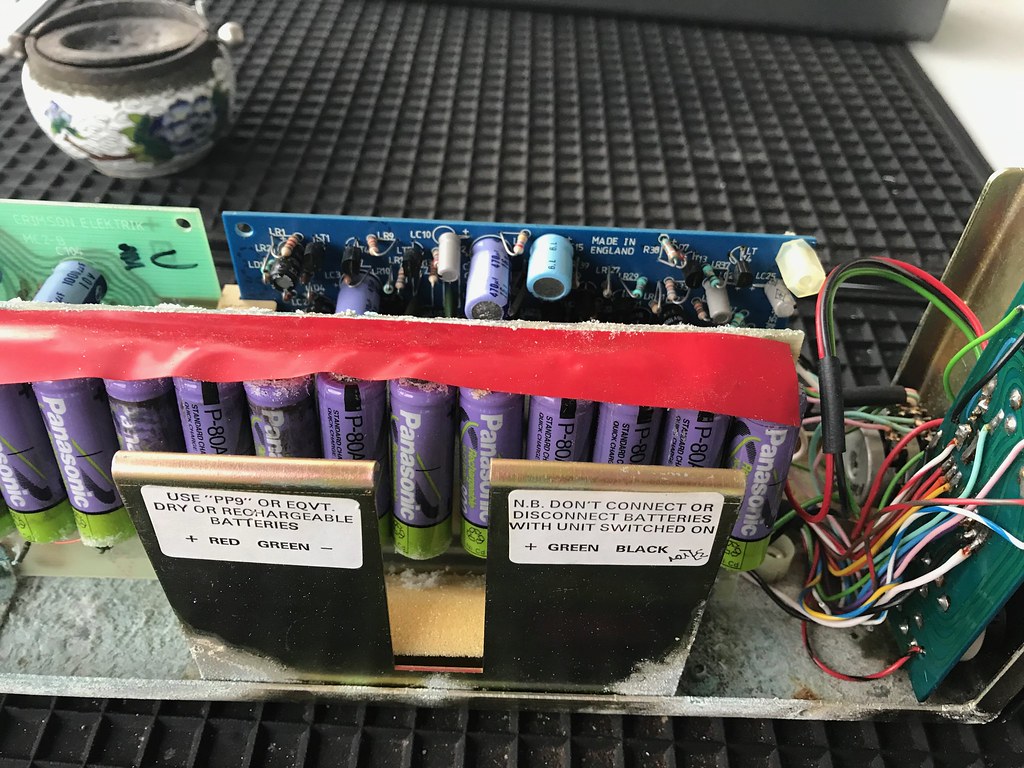
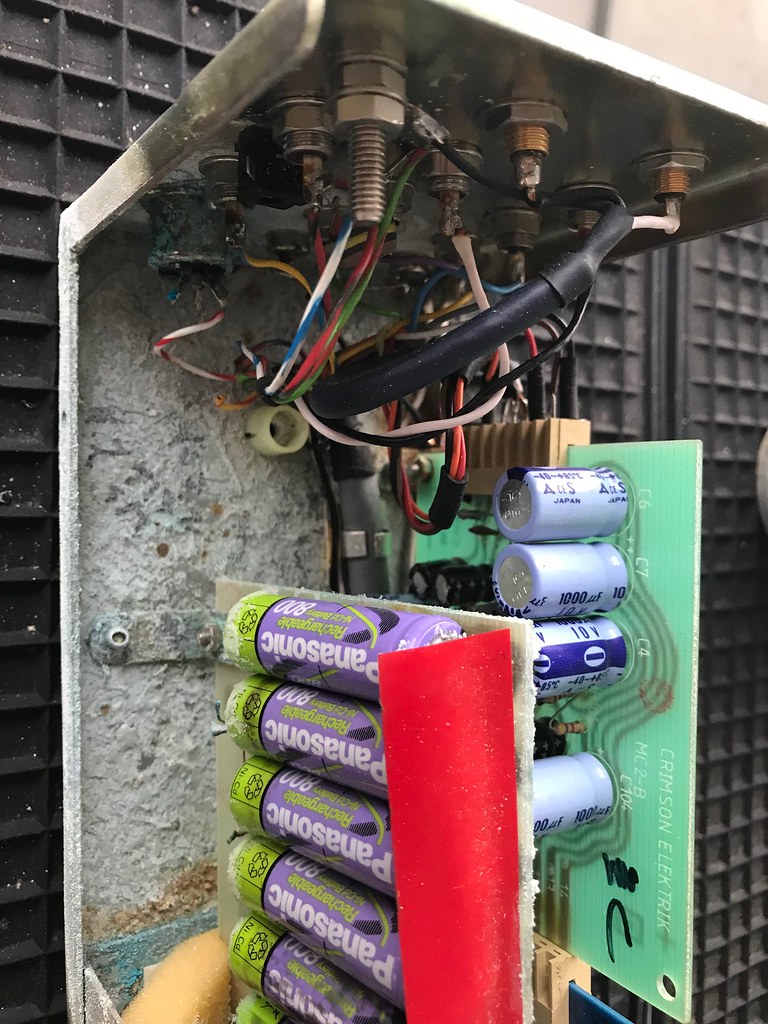
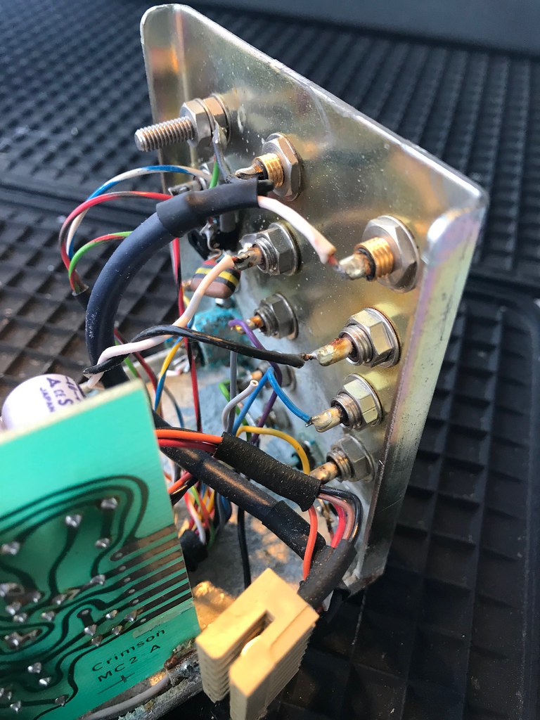
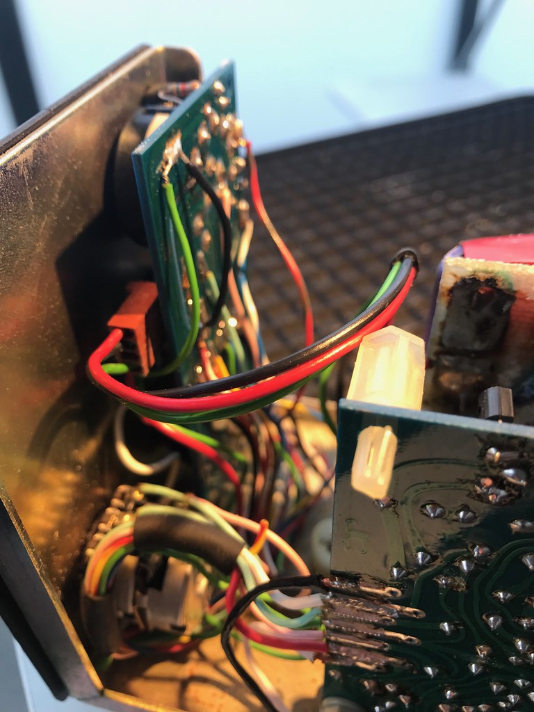
With an MC-2 phone board, and LEDs as current source on pre board
47654010832_cfa0b0a343_b.jpg


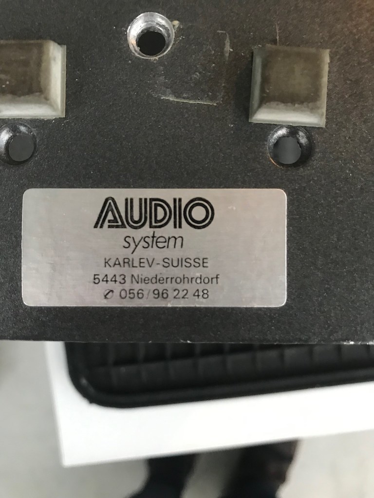
It has been modified by a Swiss audio dealer I think - dual outputs and an additional line input added I think, need to research these guys
33829615368_ebe2f8c7c0_b.jpg


Still to check the 630s, but I think they'll be fine. Can't wait to actually listen to them, powers have a pretty good reputation I think.

Richard
 
I've heard of green electronics but that's taking it too far!

The power amps are the stars here yes and pretty good. Sound very like Exposure from memory. Pre is not bad but now't to write home about...
 
Were they PP9s originally? - the PCB holding the AAs is branded Crimson, so I assume it was a factory change. Not sure if there is a list of serial numbers with years amd versions anywhere?

The mods to this one (I can so far see) are limited to a second output set of RCAs, and an additional line in. The input selector still looks original, but clicks into 7 positions now rather thank original 3 - looks like someone removed the restrictor pin and wired just one more input.

I’ll keep the pre stock I think, just clean up and fit new batteries first.
 
Of course, it also mentions PP9 on the sticker :) But strange that the AA battery board is crimson branded. Need to try and research some photos I think - the wiring loom has been messed with pretty significantly.
 
Brian Powell of Crimson has been seen on this forum occasionally

Thanks - yes, I saw, and will try and contact him I think.

Loom stripped out
46797004935_94fe2d5b9f_b.jpg


Such a mess (and a little aggressive to skin :))
47713239061_6fe0c03a1b_b.jpg

47660190802_2d54c54818_b.jpg


After a bath and gentle scrub with fairy liquid - it looks worse than it is now, the acid attacked the plating of the chassis
47660185992_d1fc20e29f_b.jpg

46796989515_10972d0d04_b.jpg

47660177102_f3c16d80d4_b.jpg


Anyone know what type and value of cap this? It broke upon removal - it fits from charging voltage input to ground, thanks
47713223711_eaf8427dc3_b.jpg


I did a little research of photos available on internet to try and see how the original red LED 610 should be wored...lordy there seem to be a lot of different iterations of both the wiring and the PCBs! My one uses casework as signal ground, but I have seen examples where that is not the case and the RCAs are all insulated from the chassis with star point back to single point - no idea if original or a modification.

Selector switches are Lorlin and original, need to see if I can find a datasheet to find out why the Power, SOurce, Tape selector on top now has 6 or 7 clicks, and try and restrict it again to only 3.

The additional input on this one has been wired in the source selector switch - while only two inputs are labelled (disk & tuner) there is a white dot as part of original etching on front panel, and switch has 3 positions not only 2. So maybe this was a factory mod? Volume pot has been replaced for a higher quality item, and at some point someone burnt out a track around power switch - I haven't traced everything yet, but I think the external walwart charger only charges batteries when power is off, plus the DIN plug is an option for a single rail supply - this is track that got burnt. Need to investigate further!

Thanks, Richard
 
Got a 610 myself and used it for a long while to excellent effect with my Nait 1 acting as a power amp (the 610 was there effectively to give me an MC input). This combo matched the Crimson power amp in the demo which was good as I couldn't afford the power amp anyway.
Well worth bringing back to life, think I have the schematic somewhere.
 
Thanks all - been offline a few days! I have the schematics, and a PM from Brian - think I will rebuild back to stock initially and go from there :) Will start re-assembly tomorrow (bank holiday here in CH) hopefully :)
 
Got as far as testing wiring today - the selector switch had 8 positions because the washer that locks the Lorlin into number of positions was in the right place...but the switch itself was in wrong position when the washer was fitted! Basically, there would have been no sound output regardless of selector position - remove washer, move switch, replace washer & only 3 positions and continuity from inputs...yay :)
 
Still been too lazy to re-assemble - just got as far as ordering new NiCD 1.2v replacement batteries - 2800mAH instead of stock 800mAH. Was going to look at LiPo replacements, but would then require a more intelligent charger than the little wallwart I have now...I’d try, but expect I’ll move at least the pre on anyhow.

And related to that a question - the circuit (linked to above) relies on far too many 10uF Electrolytics in the signal path. Normally I’d replace with Wimas or some tants I have. But as I’m likely to sell, I think I’m going to leave it stock. What do people think? Other option would be to fit new Electrolytics?

Thanks, Richard
 
If you're likely to sell it on then I'd refit electrolytics as that was the original design. It's a good preamp and has a good phono stage, no real need to change its guts.
I'd only put other types in if you're going to keep it and play about for your own interests.
 
Replacement NiCD cells arrived from China in super-fast time (one week!) so had no choice but to re-assemble. Photos later, the original cells had legs on them - I couldn't find replacements with same without paying 10 times the price, so ended up soldering wires to end caps of them. Out of 14 batteries either 1 was faulty, or I killed it by applying heat. Others were all OK and I'd ordered 20 cells anyhow so just fitted another and now have +/- 8.4v.

I realised I hadn't checked the charger walwart that came with the 610 - testing I find out it is 30v DC!! It should be AC (2 wire input from charger goes through a diode each to give a raw +/- supply, and when selector switch is in off position it passes this raw supply onto batteries)!

Anyone know what AC voltage I should use? It needs to charge 7x 1.2v (8.4v) and is passing through a single diode for rectification.

Thanks! Richard

So long as the off load voltage is well above the battery voltage it's the current that matters.... It could well be that the 30V DC is fine depending on how it's applied (ie across both sets of cells). Ideally a constant current source can be used and a simple one made from a 3 terminal regulator will work fine. Alternatively a simple resistor can be used. You will need to decide on a charge rate to give a set charge time and "C/10" is a decent rule of thumb ie charging current of 1/10th of the cells A/H capacity and usually for 14 hours.
Overcharging needs to be avoided for long battery life so if it is envisaged to leave it permanently on then you will need to charge at much less than this on the basis that only a fraction of the total capacity is used in any one listening session and it therefore only needs "topping up" by the charger. You may then choose a much lower charge rate that may take say 36 hours to charge fully from flat but won't be too much of an issue if left on charge too long. If say only 25% of the capacity is used in a session then this would still easily recharge them over night.

I'd just use mains power personally... ditch the batteries... it's easier...

Thanks Jez - but I'm not sure DC charger is right...this is the diagram inside the pre-amp (note: earth is relative - each pre board receives a plus/minus 8.4v from batteries. Here's a badly hand drawn diagram - surely it needs an AC supply?

33955821478_32ab0f8505_b.jpg


Thanks :)
 
What you have there will go bang. Imaginary prize for the first to see the big problem... never mind the more mundane ones!

I strongly advise you heed my last post...


advertisement


Back
Top