A couple of ideas, which you can ignore if they aren't useful - its your project after all.
From skimming the Mike King documents, one of the key things in making/tuning a transmission line is the cross sectional area of the line. If you want or need to change say the panel thickness, increase the depth of the box so as to preserve the free area.
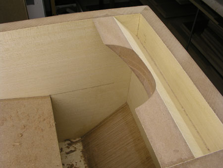
The air flow likes to go smoothly round corners. If you look at some of Troel's designs or some of Eekel's, they put curved sections in where the line doubles back on itself. Without going that far, you could add some stiffness and smooth the flow a bit by putting some triangular section fillets (cut from some triangular section beading or similar) in the front and back top corners, and in the bottom back corner. You could also round the edges on the top of the inner vertical bit of wood.