As much as the likes of "you lot" unfortunately have the right on this public forum to propagate what I consider "fake news", "alternative facts" etc I also have the right to publicly condemn this and provide correction to such things. This I will continue to do.
Much of the "fake news/background noise" is akin to people endlessly obsessing over how a 20 Tonne rated tow rope could be optimised to allow it to handle 20.1 Tonne when in fact the car to be towed only weighs 1 Tonne and there is the much bigger issue of flat tyres to consider anyway!
NOTHING before filtration/smoothing and regulators makes any difference. NOTHING!!!! Deliberately add as much noise and interference to the mains as you like... use the crappiest capacitors you can get... Zero difference.
This is why we use RC or LC or RLC filters and why we use regulators. If a million Volts could be handled then it would be easy to reduce a million Volts of "noise and interference" to well below 1Volt on the output. 120dB of PSRR is what I'm talking here and that is easily achievable by cascaded regulators and filters.
In the context of a power amplifier the kind of noise level differences on the output due to the kind of things "you lot" claim to hear will be probably way less than a millionth of a Watt (or even 100 X less than this!). This is why no serious text on electronics mentions such things and why I never see any such thing when designing my take on the absolute state of the art in low noise regulated supplies etc.
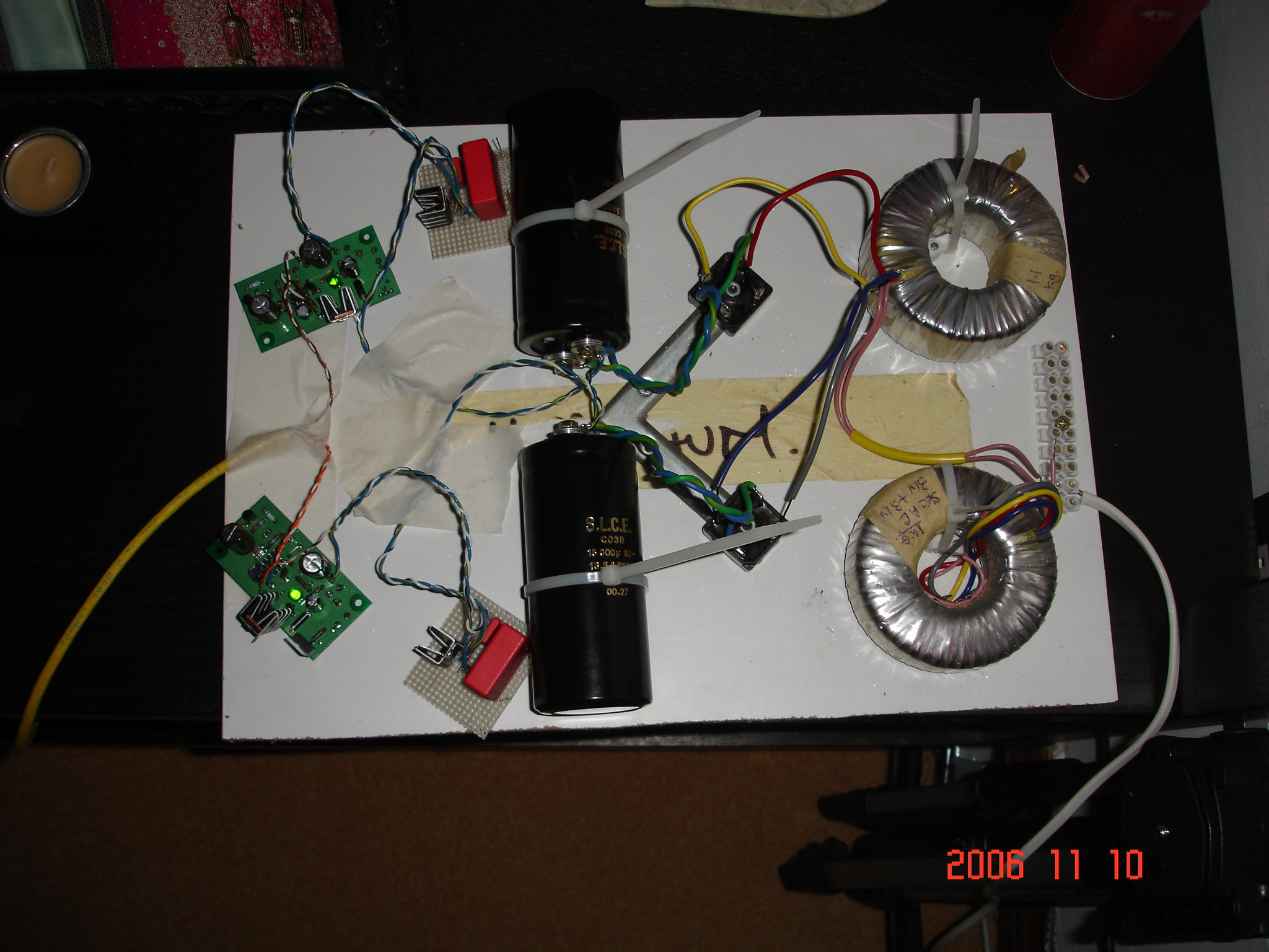
Grounding regime is critical, wiring layout important, but make and type of transformer has no effect and neither does make and type of rectifier or (assuming good implementation) whether it uses a full wave Graetz bridge or bi-phase rectification.
I'm not the one trying to re-write science and the history of technology to bend it to whatever I imagine I hear... "You lot" are the one's doing that!