
You are using an out of date browser. It may not display this or other websites correctly.
You should upgrade or use an alternative browser.
You should upgrade or use an alternative browser.
Turntable speed analysis part II
- Thread starter flavio81
- Start date
YNWOAN
100% Analogue
If someone took a recording from a Xerxes we wouldn't have to rely on hypothesis...
The lower the load on the Linn motor the closer to 0 torque it runs - when up to speed, the load on the motor is extremely small - fluctuations in that load are only a small percentage of the average load....
It seems to me that the problem with an eddy current brake is that the resistive load is itself governed by the velocity of the platter and is therfore prone to being modulated by the very thing it is supposed to be governing.
edd9000
pfm Member
Try again. I didnt realise on my previous attempt the output from the fm demodulation had clipped. Also after some reading I found a better bandwidth should be around 700hz.
I have also been experimenting with gnu plot.
Some peaks not shown at 60 and 120hz. Probably the power supply.
I have also been experimenting with gnu plot.
Some peaks not shown at 60 and 120hz. Probably the power supply.
John Channing
fruit box forever
The Linn motor obviously does perform worse under light load, hence the bearing mod making the difference to smoothness. You can feel this by holding the motor with standard vs modded bearing.
More load means more torque is required to achieve steady state which means a bigger magnetic field which means more current is needed from the power supply. I can't think of a reason why the motor would function better under those circumstances, so maybe it is the power supply that is able to function more precisely?
John Channing
fruit box forever
I have also been experimenting with gnu plot.
What is this showing and what are the units on each axis?
John Channing
fruit box forever
It seems to me that the problem with an eddy current brake is that the resistive load is itself governed by the velocity of the platter and is therfore prone to being modulated by the very thing it is supposed to be governing.
A drag (viscous fluid) based load will also be velocity dependent
John Channing
fruit box forever
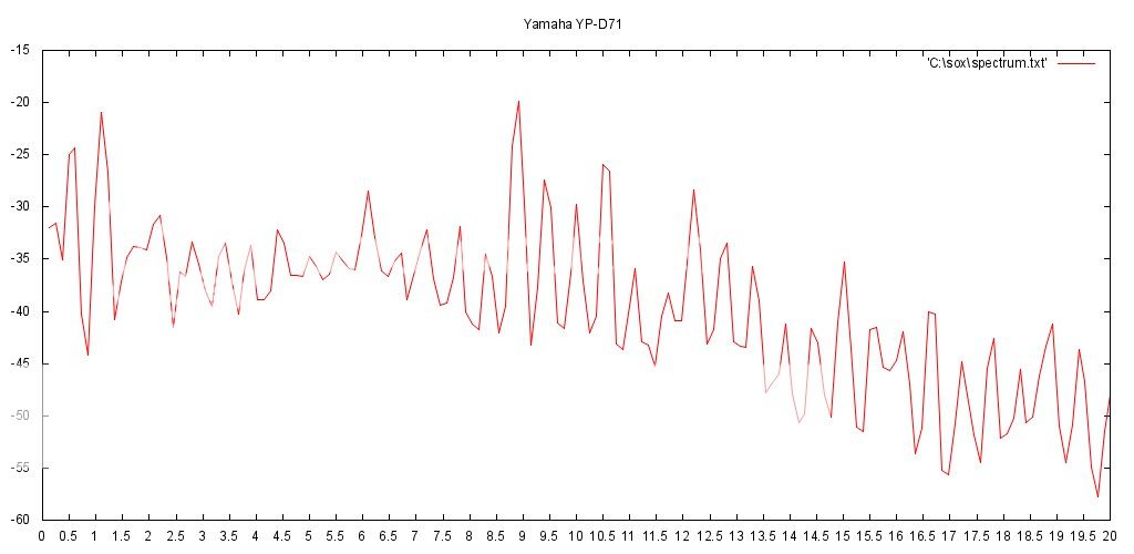
If I do a FFT on edd9000's wave file, I get this frequency spectrum. The fundamental appears to be at 3145hz (Hanning window, width 1024) and there is a spectrum of harmonics (multiples of 3145hz) and a noise floor which drops with frequency. All of the wav files submitted for speed analysis look like this with some variations in the level of the noise floor and harmonics. The question is, what causes the harmonics? Is it harmonic distortion from the cartridge or due to speed variations?

edd9000
pfm Member
Those are just the harmonics of the tone. Cartridge, tracking, the orginal tone all conrtibute to those. I cant imagine how speed variance would alter the harmonic distortion.
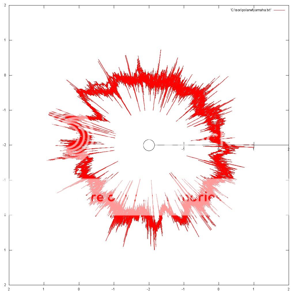
What we are doing is FM demodulating the signal, using the 3150hz as a carrier. This give a waveform of the speed variance, which can than be looked as a spectrum to locate the peaks of modulation.
What we are doing is FM demodulating the signal, using the 3150hz as a carrier. This give a waveform of the speed variance, which can than be looked as a spectrum to locate the peaks of modulation.
John Channing
fruit box forever
Those are just the harmonics of the tone. Cartridge, tracking, the orginal tone all conrtibute to those. I cant imagine how speed variance would alter the harmonic distortion.
I was surprised at the strength of the harmonics, I was expecting a purer 3150hz sine wave.
What we are doing is FM demodulating the signal, using the 3150hz as a carrier. This give a waveform of the speed variance, which can than be looked as a spectrum to locate the peaks of modulation.
I understand the process. Your carrier tone though is not precisely 3150hz, do you account for that? What affect do the higher order harmonics have on demodulation?
edd9000
pfm Member
I use a narrow window fft to find the peak frequency, then use that as the demodulation center, I think I used 3149, with a bandwidth of 700hz. I assume that means the demodulation filter bandpasses the frequency so higher order harmonics wont have much effect.
As Understand it, if its slightly off in speed, and you fm demodulate around 3150, it would just shift the amplitude of the waveform, and not change too much on the fft or polar plots.
As Understand it, if its slightly off in speed, and you fm demodulate around 3150, it would just shift the amplitude of the waveform, and not change too much on the fft or polar plots.
Paul R
pfm Member
Welcome to the reality of analogue replay.I was surprised at the strength of the harmonics, I was expecting a purer 3150hz sine wave.
Paul
John Channing
fruit box forever
More load means more torque is required to achieve steady state which means a bigger magnetic field which means more current is needed from the power supply. I can't think of a reason why the motor would function better under those circumstances, so maybe it is the power supply that is able to function more precisely?
Actually after a bit more reading on this
"as the load on the synchronous motor increases, there is no change in its speed. But what gets affected is the load angle 'δ' i.e. the angle by which rotor axis retards with respect to stator axis."
This certainly changes the shape of the interacting magnetic fields (between the stator and rotor) and therefore could make rotation smoother.
Paul R
pfm Member
It turns out that FM demodulation doesn't care what the carrier frequency is. But I cannot remember if I had to pay attention to it to do the Hilbert Transform. Things seem to work fine regardless of the sampling frequency (if you didn't know then a 48k sample of 3150Hz is indistinguishable from 96k of 6300Hz.)Your carrier tone though is not precisely 3150hz, do you account for that?
Empirically sensible results come out regardless, but I usually narrow band filter the signal before demodulation to remove noise and put the various sources on a level playing field.What affect do the higher order harmonics have on demodulation?
Paul
YNWOAN
100% Analogue
"as the load on the synchronous motor increases, there is no change in its speed. But what gets affected is the load angle 'δ' i.e. the angle by which rotor axis retards with respect to stator axis."
This certainly changes the shape of the interacting magnetic fields (between the stator and rotor) and therefore could make rotation smoother.
Yes, I agree. When considering the electrical theory one must also consider how a motor actually mechanically works.
Assuming there are load variations within the drive system, consider how those variations may interact with a motor running at near zero torque.
John Channing
fruit box forever
A fresh copy of the Ultimate Analogue Test LP arrived today so here is my 3150hz file. I had a quick look at the output and my deck appears to be running very slightly fast, but I would be very interested to see the polar plot.
Turntable Details
Linn LP12 Black Ash 1989, Cirkus + Trampolinn
Linn Lingo mkI 1991
Linn Akito mkI 1991
AT OC5
Turntable Details
Linn LP12 Black Ash 1989, Cirkus + Trampolinn
Linn Lingo mkI 1991
Linn Akito mkI 1991
AT OC5
YNWOAN
100% Analogue
A friction (viscous fluid) based load will also be velocity dependent
But not in quite the same way.
sq225917
Bit of this, bit of that
I'd be interested to see which is more linear, viscous drag or eddy current, I'd expect the eddy current brake is far less linear in terms of drag/speed. I'd also presume viscous drag is closer to being near constant for a fixed rotational speed, but I'd like to see some numbers.
But I do think some drag is better than none, and not by a small margin.
But I do think some drag is better than none, and not by a small margin.