advertisement


sme 3009 armboard/tracking issue?

jan tomczak

pfm Member
Hi all,

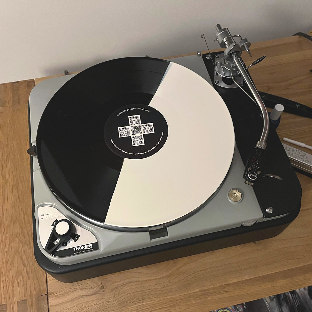
Ok, so i have my new garrard plinth and it looks great. The cutout dimensions are standard for an sme 3009 arm and tt.


I'ts not fully set up yet as i have an issue i think...the armboard is fixed to the plinth and the arm extended fully to the rear of the cutout,when i place the stylus in the protractor pin hole it't not aligned with the lines on the protractor and if i do align it with the lines then the stylus is about 2-3mm behind the pinhole.


So schoolboy error somewhere? It's like the armboard cutout needs to be a little further towards the rear, no? :confused: What do i do? Any advice would be much appreciated

Be gentle...1st time tt user.
 
Looking through my library of pictures with 401/3009 it does look a little close. Did you DIY the plinth yourself and able to move the slot?

Parallel to the deck isn't the ideal position, but it does work for most carts. By the nature of the sliding base, position isn't critical, I usually aim for 212mm @ the centre of the travel.

As a work around, could you try a headshell with slots? You'd get it running with correct geometry while you decide what to do?
Hi,
Plinth purchased from an ebay seller...i feel i need to do a bit of diy...ie file or sand out the cutout to move the armboard further away so stylus f
its protractor as in sme diagram.

Don't have any other carts to play with...
 
It looks like a very nice plinth, but as a one-time 3009 user, I'd agree with divedeepdog that the cut-out position for the arm base doesn't look ideal.
 
Sadly that looks like the plinth geometry is simply wrong. Any chance of getting a refund? If not you need a woodworker of some description.
 
Sadly that looks like the plinth geometry is simply wrong. Any chance of getting a refund? If not you need a woodworker of some description.
Yes, i'd have to agree with you, armboard cutout too close to tt. i have messaged the seller...and see where we go.
 
If re-specifying a plinth I’d strongly recommend putting the cutout at a radial angle to the spindle rather than square to the side of the 401 chassis. It allows for much more actual movement. If I’d designed that plinth it would be an inch or more wider and the armbase would have a lot more room.
 
If re-specifying a plinth I’d strongly recommend putting the cutout at a radial angle to the spindle rather than square to the side of the 401 chassis. It allows for much more actual movement. If I’d designed that plinth it would be an inch or more wider and the armbase would have a lot more room.

Agree completely but I see there are numerous official 3009 pivot to spindle distances all the way from 211 to 216 depending on which model:rolleyes:
 
Out of curiosity, can the arm tube not be loosened and shifted by 3mm towards the rear?

Message from seller is that the measurment was 215.4mm from spindle to the centre of the sme hole, just checked myself and it does seem to measure that...

Is it possible iv'e flattened the stylus a little by being clumsy and that's what's causing the mis-alignment?


Agree completely but I see there are numerous official 3009 pivot to spindle distances all the way from 211 to 216 depending on which model:rolleyes:

Yes, there are certainly differences, and that is before the (far rarer) 10” SMEs are factored-in (they are actually 9.5”).

The 3009 geometry changed from Stevenson to Baerwald at some point quite late in the Improved run, I think at the point the Series III appeared. Not sure if the recommended arm position changed at all. Regardless with the slot radially positioned there is a huge amount of movement, about a 12-15mm from the centre point in either direction. Certainly way more than in any slotted shell.

51759926235_f6981c12ce_b.jpg


My pre-Improved 3009 ends up a fair way back aligned with its Stevenson protractor, but that is purely down to the TD-124 being quite constrained space-wise so the centre of the slot isn’t quite where it should be. It still happily aligns any cart I’ve tried, so no issue. There’s still a couple of mm slack to play with.

PS I can’t remember which way it moves things (my maths is terrible), but it may be possible to get an acceptable alignment in the 401 plinth upthread by using a Baerwald protractor and very slightly skewing the cart in the shell. I know the inner null for Stevenson is roughly 60mm and Baerwald roughly 66mm, so it might be worth a try. It will either make it better or worse!
 
The linked alignments (Lofgren A,B and Stevenson) take the pivot to spindle as low as about 209.9 from the SME alignment of 213.5.
Offset angle goes from 22 to 24.

215.4 is basically the later S2 Improved (Also my Mission 774)
Of course the other variable is the cartridge mounting point to stylus dimension - flattening the cantilever angle shouldn't make a difference of more than about 0.5mm
 
Where are you? Perhaps a local Fishie with Dr Feikart protractor could measure accurately?

Best case if it becomes an argument with the plinth builder.

Another anecdote, although I think it applies more to earlier arms is the arm could be off spec, we are dealing with British engineering from the 60’s :)
I'm in Bedford, would be handy if some local fishie reads the post...i'll see where i get with the seller, don't particularly want to hack at the plinth myself...
 
If re-specifying a plinth I’d strongly recommend putting the cutout at a radial angle to the spindle rather than square to the side of the 401 chassis. It allows for much more actual movement. If I’d designed that plinth it would be an inch or more wider and the armbase would have a lot more room.
Ok, thanks. I'll look towards a radial angle cutout as a better option.


advertisement


Back
Top