advertisement


RJM Emerald Phono Pre Build

jagdesign

pfm Member
In attempt to reduce box count, I decided to build the RJM Emerald phono stage, but with the addition of an input selector and stepped attenuator. This should reduce my current box count from Denon HA-500 head amp > EAR 834P > Input Selector, to just the one box, plus my DAC.

After a couple of teething issues with the PSU circuit, I got everything up and running, however there is some faint hum when the phono stage is on, and selected, which doesn't really change with the attenuator position, and is audible with it completely closed/down. Switching to the DAC input or turning the power off, there is no hum whatsoever.

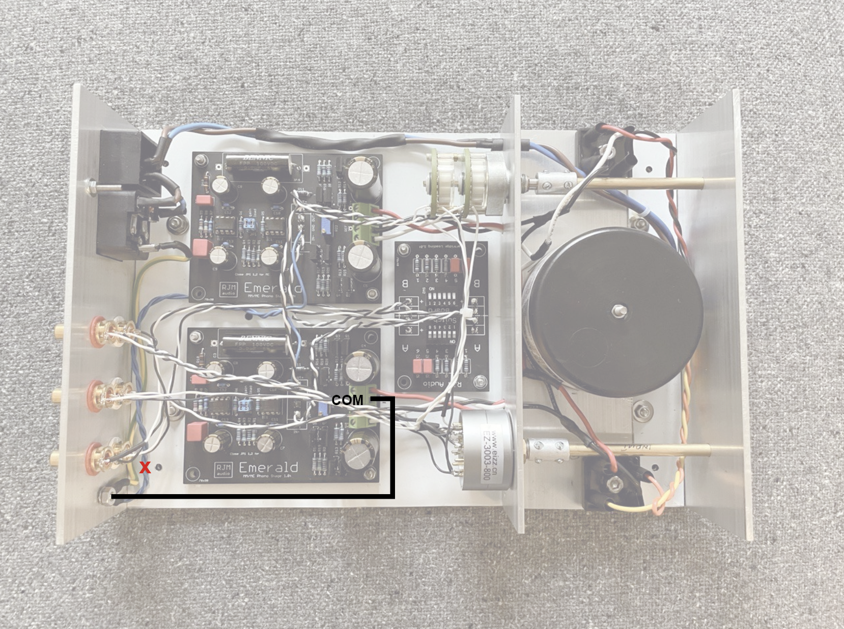
The designer, Richard Murdey has a great 'helpdesk' thread over on diyaudio, however we are still struggling to remove the hum https://www.diyaudio.com/forums/ana...ald-phono-stage-help-desk-60.html#post6818558 Richard kindly analysed my recording of the hum from my speakers and it appears to be 100Hz, leading him to believe that there is likely some DC coupling. With the hum only appearing on the phono output, and regardless of attenuator position, Richard mentioned it could be the wires between the attenuator and input selector. I've just tried moving these around with the attenuator detached from the chassis - no cigar.

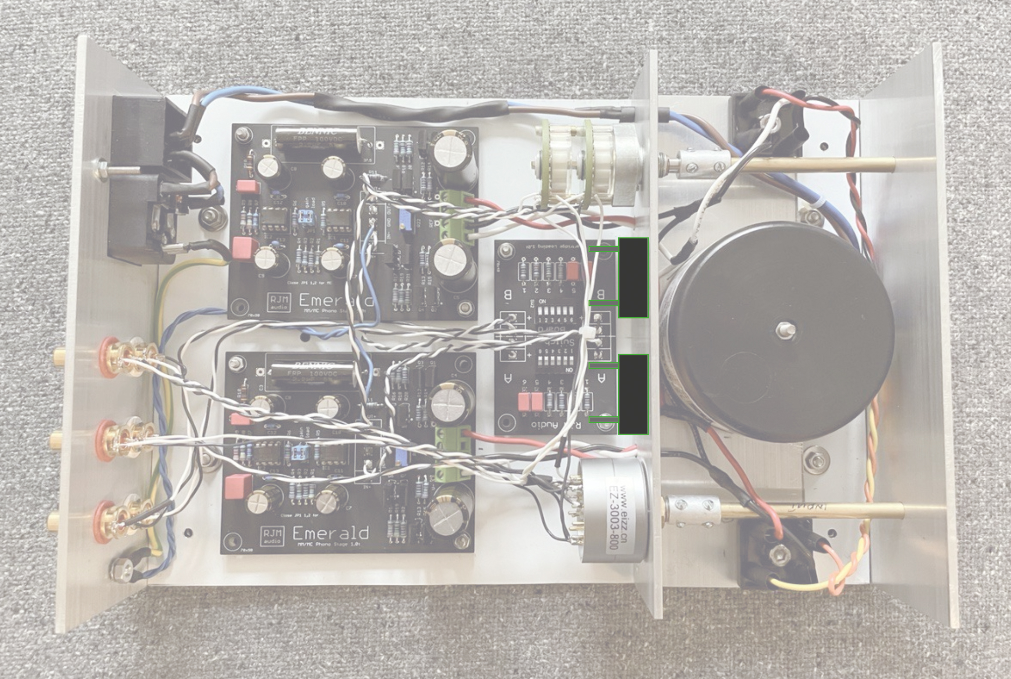
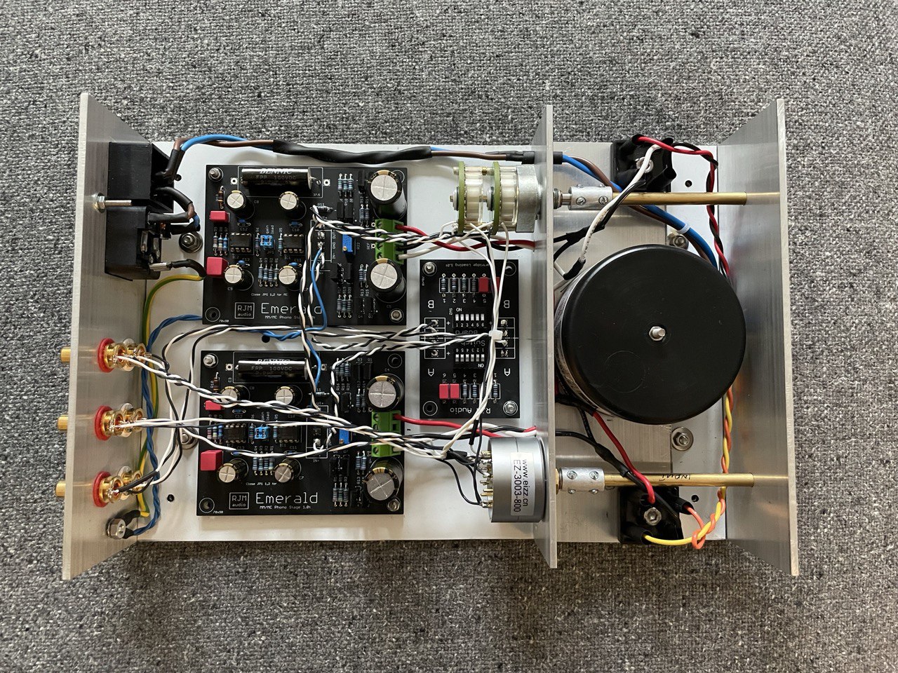
This is how it currently looks, I welcome any thoughts on what/how/where to try and sort this (comments on heeding the designer's advice and building a two-box setup with separate PSU will be politely ignored :D)

p1r00rY.jpg
 
What if you take the stepped attenuator out of the equation and find out the hum culprit without it? Then add It again.. Not really a scientific solution but maybe worth trying?
 
I've built five of these so far and all are quiet. Two of them are single box builds. I used HackerCaps instead of Richard's rectifier board as I felt it better to feed each phono board with clean dc. You do have rather a lot going on in that enclosure.
 
The wiring from the rectifiers will be carrying rippling dc not clean dc and you have them wrapped around the control spindles and the phono stage wiring. The rectifiers are possibly too far apart as well.
 
@geoturbo yes, this has crossed my mind although it's a bit of a pain to do and I'd need to introduce a pre to the chain. I do have a Quad 34 I could dig out so it's possible, but ultimately I need the attenuator in there. I am wondering if I have it wired correctly - I have the Emerald signal grounds going to the Goldpoint's grounds, then onto the input selector where all the input grounds are tied together. I think I have seen other people tie the signal grounds together at the phono sockets - can't really see how this would make much difference though?

@Chops54 ah interesting, good to know there's another user on here! Yes it's a bit tight in there - I had a leftover Naim shoebox sleeve which I've been itching to use for something, so thought I'd try and get everything in there. I had seen some single box builds on diyaudio, where the owners reported good results/no obvious hum, so thought it worth a go. Maybe some regulation would help things...
 
I built one of mine into a shoebox but I don't have all that switching and stuff. Mine is single input only and I have parallel phono sockets to do the loading instead of using the loading board. I also have two trim pots instead of one to balance the rails so I can adjust each rail independently. I'll try and post a pic before I retire to bed.
 
The wiring from the rectifiers will be carrying rippling dc not clean dc and you have them wrapped around the control spindles and the phono stage wiring. The rectifiers are possibly too far apart as well.

The hum was there before the input shafts were in place, and doesn't seem to have changed after installing them. I didn't realise spacing between the rectifiers was important - what effect would that have?

As per the diyaudio thread, I tried disconnecting the DC inputs to the Emerald boards, and turned the power on - there was no hum through any of the inputs.

The hum is also there with the stepped attenuator fully closed, which as led Richard to suggest that it's the wiring somewhere between the attenuator output and phono sockets. He mentions the Emerald power supply coupling noise to the attenuator output, but I'm not sure if he means the DC wires in to the Emerald, or the power supply components on the Emerald boards? Moving the attenuator towards the back (away from the DC power lines) doesn't seem to help, but the noise doesn't seem to get worse either.
 
It's only a gut feeling but with the rectifiers so far apart it makes the 0 volt connection rather long. The closer together they are the lower the impedance will be.
 
Aha, and lower impedance should = less ripple?

I do have a Super Teddy Reg that I bought from here ages ago that's been sitting unused in a box. Would it help to employ that?
 
Don't braid the dc to the emerald boards, twist em, tightly. Raise the emerald boards on longer stand offs and run all power wiring on the floor and all signal wiring in the air, raise the switchboard as well.

Shorten your loop area after the rectifiers as much as possible.

And contrary to Richards preference, isolate the gnd post from the chassis and run it to signal gnd on one of the channels, keep a real chassis safety earth back to iec completely separate.

I suspect that much stuff in one small box will never be quiet.

I've built two emeralds, never anything more than a bit of feint rustle with the pre amp at full tilt, MC gain set at 64db on the emerald..
 
Aha, and lower impedance should = less ripple?

I do have a Super Teddy Reg that I bought from here ages ago that's been sitting unused in a box. Would it help to employ that?


I don't think the TeddyReg is of any use here as there's already good on board regulation. You need something like a HackerCap to feed clean dc to the phono boards. Imo if you want to build it all in one box as well as a clean dc supply you need to keep the whole psu at one end of the box and the phono section at the other and avoid mixing the wiring.
 
Nothing to do with the hum, but I'd like to see grommets on the wires where they pass through the divider panel, and bushings on the shaft extenders where they pass through the front panel.
 
@sq225917 Thanks for all the pointers. I've just ordered some standoffs, but I'm struggling to understand how raising the boards will help as the hum is present with the attenuator completely closed (zero output)? I'll see what I can do with repositioning the rectifiers and better cable dressing after the boards are raised.

I did see your posts over on diyaudio regarding the grounding scheme. I didn't have the board grounds connected initially, then did to the ground post, but again, it didn't seem to affect the hum I'm experiencing - I can give it another go though after trying some of the other tweaks.

@Chops54 good to know re the STR - that can stay in it's box for another 10 years or so then :D
 
@jagdesign throwing in a couple ideas to shorten the signal path putting the switchboard standing right above the Emerald board close to the input Rcas? And that would free some ground to have the bridges closer maybe or for a tiny psu prefiltering stage?
 
I think your 0v PSU wiring in conjunction with the coupling to mains earth makes a loop. I can't see how you are wiring the 0v signal out, but if left and right get joined somewhere there too then you have three divergent connections between L 0v and R 0V, one of which has relatively big currents flowing in it.

I don't know what the best options are, but this smells to me.

I'd probably try removing the mains earth connection to 0v, if you end up wanting that then perhaps straight to the output phono sockets. See if that makes any difference.
 
You need to move the reservoir caps up close to the rectifier bridges, so the relatively high noise current loop is all on the dirty side of the panel.

The loop between rectifiers, caps and earth returns should be as small as possible. Ask your helpline for instructions on how to do that.
 
Thanks for the comments guys. It sounds like moving the rectifiers to reduce the length of the 0V line would be wise. Would it be a terrible idea to mount them on the dividing wall rear face, near the switchboard, like this?

uWNUILL.jpg


@geoturbo I might give moving the Switchboard a go, but would need to rejig quite a bit to make this work, so will try the PSU changes first I think
 
Yes, as @Paul R and @sq225917 have said, if your input signal earths are connected together somewhere (taped bundle just behind the selector?) and you have the 2 blue wires from the common earth also going back to the boards, this forms an earth loop.
Edit: hadn't realised, but it looks like you are rectifying both halves of you DC separately and have a common wire between the rectifiers, as well as the blue wires to earth and the white signal 0V wires.
 
@a.palfreyman The input and output signal earths are bundled together on the input selector as you mentioned, but I don't see how this forms a loop when only the GNDs from the boards are connected back to the chassis ground/mains earth point? The phono sockets are all isolated from the chassis, maybe I'm not understanding correctly? I do wonder if tying the signal -/grounds together at the sockets would've been a better idea?

As mentioned over on the diyaudio thread - removing one of the COM (black wires from the rectifiers) from the boards, kills the hum. As per Richard's suggestion and shown below, I have tried taking another COM wire to the chassis Earth point, and removing the board GND connections, but that doesn't sort it.

rTvF3dt.png


advertisement


Back
Top