advertisement


Revisiting Jim Rogers JR149s

0.4 Ohms sounds reasonable, what reading do you get when shorting out the meter probes? If there is a reading, you need to subtract that from your reading of 0.4 Ohms. Unless one can see evidence of burning, I guess that the inductors will be fine.

Cool. My meter (a Fluke 17B) zeroes with the probes shorted, occasionally hitting 0.1 Ohm if left for a while. My gut feeling is the inductors are ok. The meter is a bit slow to react and some of the inductors read at 0.5 to 0.7 when left for a while, including the one next to the burned resistor (which is also directly connected to that resistor).

PS I’ll buy one of the linked meters. Looks useful, though I doubt it will be here before the resistors & caps and I start rebuilding.
 
I’ve ordered the stuff; Kiwame resistors and Mundorf MKP (250V) film caps, which will be a really tight squeeze, but should hopefully fit! They are fatter than the ones there now, but a little shorter, so moving them as close to the outer edge of the board as possible should do it. I think the Kiwames are maybe just a little bit narrower than the JR resistors, which again will help.
 
Nice site, but I just can’t see the colours on the actual resistors accurately enough (partially colourblind)! It’s actually one reason I go with the Kiwames as they have the value written in text! Otherwise I have to use the meter to select resistors.

I guy I worked with for nearly 20 years at GEC Marconi was a bit colour blind, only found this out towards the end.

I looked at your photos and was not absolutely sure about all the colours on the resistors.
 
I looked at your photos and was not absolutely sure about all the colours on the resistors.

Welcome to my world!

PS Just desoldered the burned resistors and neighbouring cap to assess the board. Annoyingly the resistor burned small holes under them through the surface of the board, but not right through so the tracks are fine, as are the pads. Its just ugly (which still annoys me as I’m so crazy obsessive/perfectionist about this restoration stuff) rather than anything functional. The two resistors, despite looking like crap, still measure *exactly* 22 Ohm!
 
I’ve just given it a good clean with IPA and stuck a bit of unprinted Dymo tape over the slight hole which at least makes it look neater. Once the resistor and cap is in place it shouldn’t be visible. Thankfully the solder pads on the other side are still all perfect. I’m really surprised that amount of heat didn’t lift tracks etc.

The damage some folk do to their audio kit never ceases to amaze me. The JR149 is a little near-field mini-monitor suited to listening to sensible music at moderate levels, how the hell does a resistor get so hot it actually burns the top surface of the crossover? WTF did they do to it? I hate to think what condition the drivers would have ended up in!

The Quad 303 can very seriously overheat if it doesn’t have proper ventilation and airflow, e.g. if someone blocks the bottom vents by sitting it on a carpet or whatever rather than a table. It needs the full clearance allowed by the hard plastic feet.
 
I understand that the BBC got a lot of burnt resistors in LS3/5a's by fast spooling tapes with the playback head still in contact with the tape. This generated a lot of HF, or perhaps VHF! cooking resistors and T27's. Indeed, a few years ago my friend's son, a BBC engineer, managed to get from work a pair of LS3/5's with burnt out T27's.

I always stand my 303's on a hard surface, knowing about the carpet problem.
 
I guy I worked with for nearly 20 years at GEC Marconi was a bit colour blind, only found this out towards the end.

I looked at your photos and was not absolutely sure about all the colours on the resistors.
In my GEC McMichael days out of a team of 5, I was the only one with normal colour vision, so I was official resistor reader.
Even then telling red from brown, orange from yellow and grey from white can be challenging. Some very poor inks have been used
 
48712294456_ede1667c6a_b.jpg


Second set of crossovers with new resistors and caps fitted. The Mundorf MKP are a tight fit in places but clearly doable, I suspect they represent the largest size that can sensibly be fitted.

First impression is not a huge change by any stretch, but maybe a little more detail/layering. One CD I played was some of Isaac Pearlman’s solo Bach violin and I felt more aware of the violin being in a real 3d acoustic space and how the reflections worked. With other (rock/pop) CDs I’ve not been aware of that much difference, but this one sounded far better than I remember it, just more nuanced and real somehow. I played a bit of Keith Jarrett too, and that sounded seriously good too, again I think it is placing things into a more coherent three dimensional space and layering a little better. I’ll try something orchestral later, I’ve been playing Sibelius 7th a fair bit lately, so maybe that. Need some string quartets too.

I initially started with the stock fuse, but once I figured out the crossovers were fully functional I reverted to the bypassed monster I picture upthread somewhere. I’m now in no doubt whatsoever that is an improvement and would recommend doing similar or hard-wiring the fuse-holder out. It just brings more gravitas and dynamics.

The treble pot is set exactly at its mid-point as per the other pair, I may end up backing it off just a tiny bit, but its not far off right. I need to listen a lot more to make that call. I need to go back to the other set too just to make sure I’m not imagining anything (the reason for doing it this way in the first place!).
 
Spent some more time listening and whilst I hate committing myself without going back and forth a few times (which I won’t do until these have ‘run in’ for a month or so) I’m pretty sure the new Mundorf poly caps do improve over the Alcaps.

I’ve just spent the last half hour dialling in the tweeter level pot, which really is remarkably sensitive. I’ve been fiddling between the pot perfectly centred at its mid-point and maybe 2-3 degrees under, and just within that narrow range orchestral strings go from wrong (tad dull), to right, to wrong (tad bright). I think I have it sorted now, everything sounds in its correct place and seems ok CD to CD. I’ve been using a mix of classical (orchestral, chamber and solo violin) and jazz (ECM) as my reference point with a bit of well recorded rock just to double check (Donald Fagen).

My feeling at this point is that the crossover upgrade has purged the last tiniest hint of ‘Kan quack’ or forwardness the 149s possessed, opened up the spacial information a little (which was already superb) and just brought more detail, layering and dynamics. I do think I’m hearing a little more information, plus that thing that 149s do where you can stare at them and they seem to have absolutely nothing to do with the music as nothing seems to be coming out of them is enhanced a little further. Certainly nothing night and day, but likely a worthwhile incremental step. The good thing is I’m not at this point hearing any negatives, though again I’ll revert in a month or so to cross-reference and make a decision.
 
Part of me is hoping the improvements you're hearing are imagined, if only to avoid sparking a selfish compulsion to follow suit and upgrade my JR crossovers! Guess we have to wait for your update in a few weeks when you revert back to the stock crossovers to know for sure...
 
Had another good listen last night and I’m pretty convinced the mid and top are clearer and more ‘3d’, and I think I like this. I’m becoming slightly less convinced with the bass and suspect I may have lost just a little warmth/weight that exists beyond the reach of the treble level control. They sound exceptionally ‘fast’, but maybe a little drier than I’m used to. I don’t know what the caps on the bass do that could give this impression, but I do feel a little warmth and ‘bloom’ is missing. It will be very interesting to go back, but I want to run them a fair bit longer before doing that to really get used to them.

I’m sure I’ll eventually end up making one really good pair out of the two sets, and it wouldn’t surprise me if the best compromise wasn’t electrolytics on the bass and the two Mundorf 3.3uF on the tweeter. If my feeble attempt at reading the schematic and following tracks is correct these are the two either side of the 5.6R resistor and positive terminal. If my hunch proves accurate after going back and forth a few times I’ll just swap them to the original boards along with the cleaner looking level pots.
 
Tony
it wouldn’t surprise me if the best compromise wasn’t electrolytics on the bass and the two Mundorf 3.3uF on the tweeter.
Thats what I did with my xovers, electrolytics on the bass as they only filter off the HF and Polyprop on the tweeters

Had another good listen last night and I’m pretty convinced the mid and top are clearer and more ‘3d
That was my observation also

I later replaced all resistors with mills and noticed a further improvement in clarity
I also did away with the 4 pin plug and hard wired mine

Alan
 
Ok, weak-willed as I am I did exactly what I said I’d not do for a while and stuck the original crossovers back in. I just needed to cross-reference for my own sanity...

Everything I felt above is absolutely right aside from the degree and balance. The differences are bloody huge! First thing is the bass, it is just miles better with the original electrolytics, way deeper, warmer and more powerful, they just sound like a much bigger and better speaker. As such I now question my ability to make a proper judgement on the treble as by effectively ‘turning down’ the bass (and to a surprisingly large degree!) it will inevitably have drawn attention to the treble and upper mid, which certainly did sound more 3d and detailed, but also thinner.

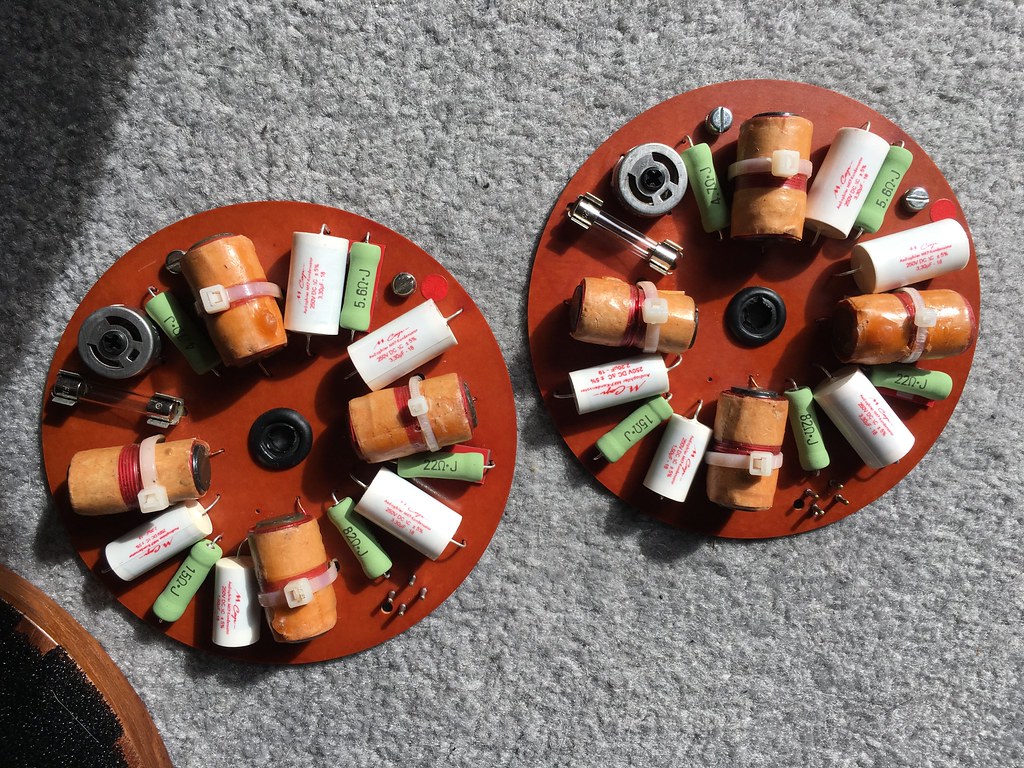
I’m listening to the original crossovers now and wanting for nothing, so the next decision is whether to try the two 3.3uF Mundorf caps on the tweeter. I suspect I will try that, but maybe not immediately. I want to just get used to how the speakers were again first as they sound so coherent and together. I also want to see how easy it is to desolder the far nicer looking pots on the ‘new’ crossovers as ideally I want to make one ‘perfect’ pair out of the two sets. I’ll have a go at that later...

The problem with this is I am fairly convinced by component burn-in and I have only given the new caps about four hours, whereas the other pair of crossovers have had many hundreds. Even so the bass weight thing I’m hearing is too big for that, surely? Component burn-in is usually just a slight relaxing, not a huge thing.
 
I swapped the pots over. Just cosmetic as all measured as expected, but that rusty one had been bugging me for years. I need stuff to be right! A far easier job than I was expected, just a couple of goes with the spring solder sucker on each pad and they fell right out. These are actually really nice quality boards, I’ve not had even the slightest hint of a pad wanting to lift on either set.

I’m not going to do anything else until my inductance meter thingy lands as one thing that occurred to me is I haven’t really proven they are ok on the second set of boards, and if not it may possibly explain the drier leaner bass. I’ll measure them all when it arrives. If all look ok I’ll accept my subjective findings above and then try the two 3.3uF caps on the tweeter in my ‘good’ set of boards leaving the bass as is.
How did you measure the pots?
 
How did you measure the pots?

Multimeter on Ohm setting whilst out of the circuit (i.e. after I’d desoldered them and removed them from the boards). I was curious as to where they were set and how accurate left to right a visual setting was as much as anything (very, if they look the same they measure the same within a point or two of an Ohm). If I was measuring things sensibly (a big if!) I seem to have had them all set to between 29-30 Ohm between the centre and what I think is pin 1, but may well be pin 3! I took the opportunity to give them a good blast with Deoxit too. They all definitely work as you can see the value change as the wiper moves. Swapping them was just a crazy OCD thing, all four are absolutely fine!

I do want to experiment more here as the behaviour of this control is rather strange as highlighted by Jez’s reverse-engineering the crossover on one of the other JR149 threads. That revealed it isn’t a simple more/less thing and impacts the filter’s knee or ‘q’ somehow. I’m still trying to figure this out but my guess based on subjective findings is that its job is more to do with filling the ‘notch’ left by the B110’s ‘quack’ filter and getting that range seamless. I certainly find very small movements of this pot quite profound in effect. It really impacts the bow of a violin, how strings sit in an orchestra, vocal sibilance etc, i.e. somewhere around 2-4 kHz by my reckoning, though moved to extremes it obviously brightens/deadens the full treble range. I consistently end up with it just slightly to the dull side of the mid-point of its travel, but only by about a degree or two. It is almost centred.
 
Modeling while actually taking driver impedance into account is hard to get accurate.
Simply making a careful acoustic measurement before and after using a microphone is a better method for most people.
Just mark exactly where the speaker and microphone are placed.


advertisement


Back
Top