advertisement


Retro chip tester project

Tony L

Administrator
I don’t think I’ve ever started a thread in this room, so I may as well start now by documenting this project:

52736890316_f7ae8a868b_b.jpg


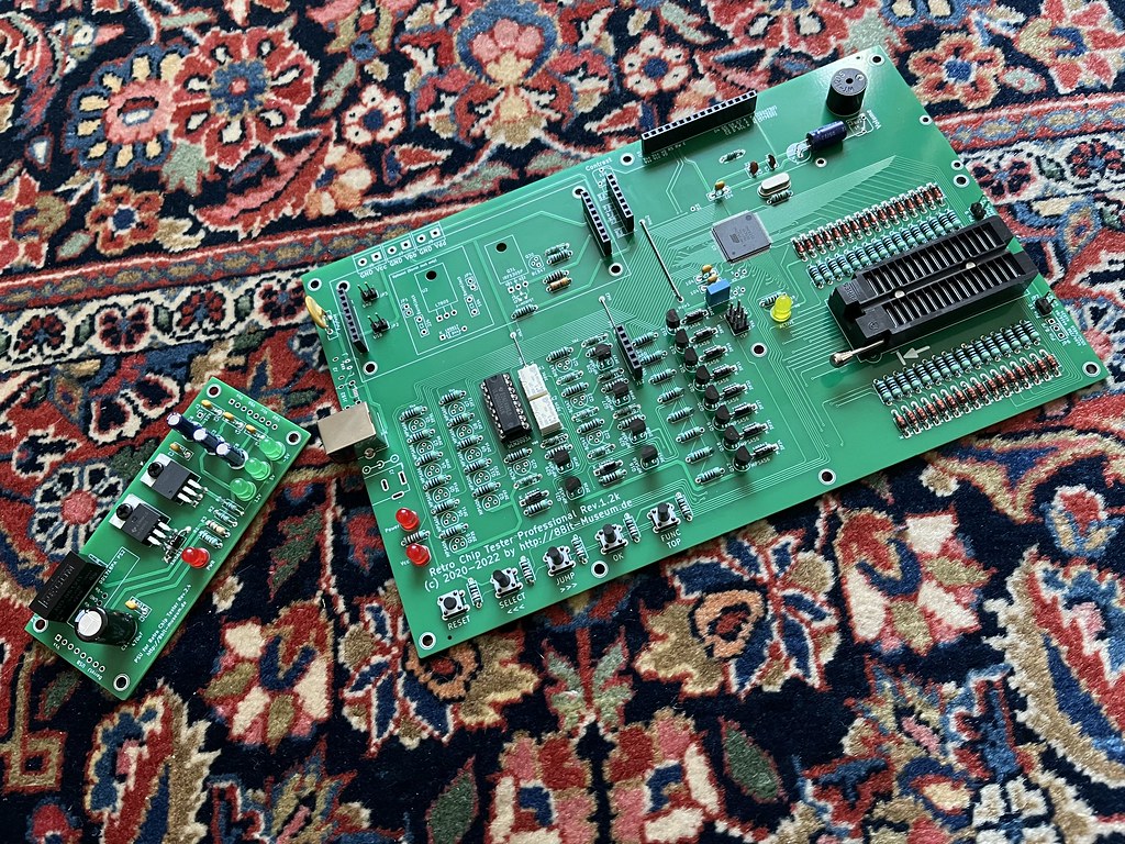
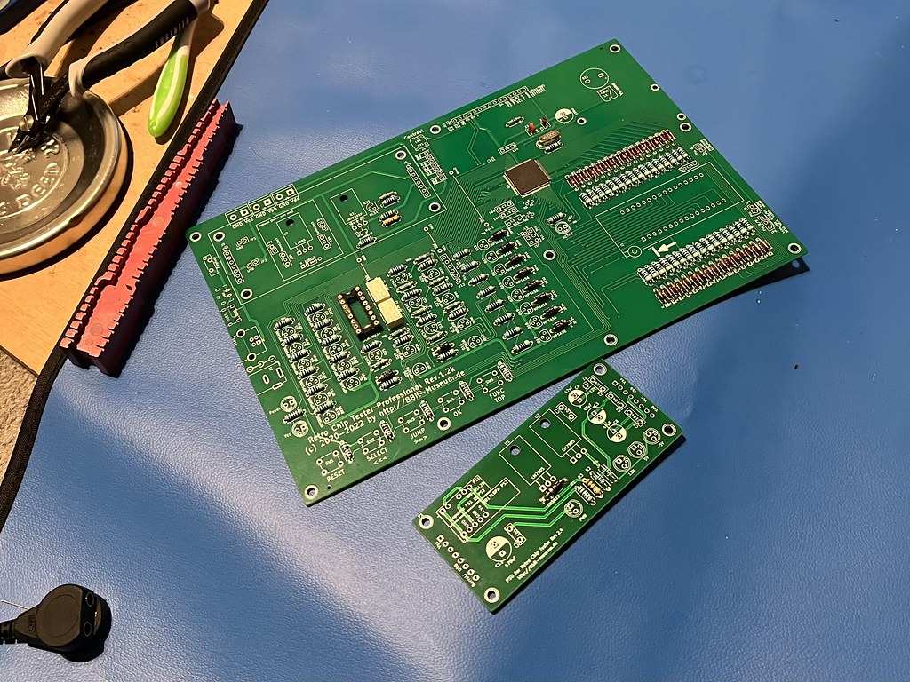
It is hopefully going to be an 8bit-museum.de Chip Tester Pro.

I hit the first big snag when trying to order the bill of materials as the German supplier where the shared basket was stored will not deal with the UK thanks to Brexit. Thanks Brexit. I managed to find a part compiled basket at Digikey and I think I’ve now got about 4/5ths of what I need to throw it together, maybe a bit more. My plan is to build everything I have once it arrives and that will make it easier to figure out what is missing as there will be empty holes!

I opted to have the pre-flashed CPU installed as I didn’t want my first attempt at SMD to be this fiddly or expensive. This isn’t a cheap project, I suspect I’ll be edging towards £200 by the time it is done, but it should vastly improve my ability to tinker around with vintage computers. It can test a vast range of RAM and logic chips, pretty much everything one would find in a BBC Micro, Apple II, Spectrum, C64 etc and may have some uses within audio, I’m not sure. I thought I’d stick a thread here anyway just in case it is if interest.

The Digikey stuff should land next week sometime.
 
I should be able to make a lot of process next week when the Digikey order lands. I’ve gone through and compared the bill of materials against what I ordered at Digikey and I’m missing two transistor types (really should have spotted that), one diode (of a type I’d ordered loads of, but missed one) and a load of pin header type things I just don’t understand the terms for. I think I’ve got everything else, which is certainly the vast majority of it. I’m going to build that as it will be far easier to assess what is missing with a semi-complete board in front of me. Especially when it comes to little connectors etc. I really want to get the remnants into one order rather than having to pay shipping multiple times.
 
52745097738_cded31d756_b.jpg


The substantial and remarkably well packaged DigiKey order arrived today. There really is a lot of it! I’ve flung the 470 Ohm resistors in to make a start. All 54 of them! That’s probably me done for the day. My plan is to work upwards in height, so finish off the resistors, then diodes, then the more pointy bits, then finally stick an order in for the missing stuff.
 
I woke up a bit, so all resistors on both boards now done! I’ll do the diodes tomorrow and post a progress pic.

PS One good tip I picked up watching someone build one of these on YouTube was to populate the densely packed rows of resistors & diodes in two passes, i.e. leave an empty space between each component on the first pass, and then go back and do those once the first ones are all soldered and lead-trimmed. Makes it way easier.
 
One thing to be aware of is when choosing a display, it’s a good idea to get a fast one, as the menus move very quickly and you can get caught out with lag.
 
One thing to be aware of is when choosing a display, it’s a good idea to get a fast one, as the menus move very quickly and you can get caught out with lag.

I’m pretty sure I have exactly the one specified in the manual, actually three of them as that was how Amazon sold them! I just followed the link in the current BOM. At least it is just a plug in module so if I can swap it for something better if I don’t like it. Was about £12 for three delivered IIRC.

You'll need a retro chip tester tester to make sure it functions correctly

This is the risk for sure! I’m reasonably skilled at soldering and it is going together very easily so far (I’ve actually got all the diodes and a few other bits in now). The problem will come if it doesn’t work as I don’t have the skills to fault-diagnose something this complex! I’m double-checking everything as I go. Thankfully the board is self documented, all values are marked, so I’m sure I’ve got everything in the right place and the right way round so far.

Here’s the current state of play (apologies for awful electric light pic):

52744707887_34d454e585_b.jpg
 
A tiny bit of advice, use a blade to scrape the legs of resistors, diodes, other components and solid connecting wires prior to soldering them in to the cct board.

This avoids cold solder connections and dry joints, it also eases solder flow using solder flux.

Hope this helps?

Edit: Tis a useful tip, scraping tarnished corroded green copper wire and co-ax cables, until you can see shiny copper before soldering.
 
I always do that to anything that looks crusty, plus give the board a good clean with isopropyl before starting. I’m not having the slightest issue with anything flowing on this project so far, it’s so much easier than some of the rework of ancient stuff I tend to do these days!

The thing I would like to learn is how better to clean flux off afterwards. I do the isopropyl and toothbrush thing everyone does, but the board still ends up sticky afterwards even after flooding with the stuff (the 99% pure stuff I use in my records cleaning mix) which is highly annoying. I’m tempted to actually wash this one up with hot water and washing up liquid after the usual isopropyl stage before fitting the big ZIF socket (and obviously without the display!). Good idea?
 
When I worked at "Dolby Labs" as a wireman in Stockwell, Souf Landon.

They had a huge oblong floor standing tank, full of some liquid chemical c/w with a lid.

Whenever I had wired up a back panel for their Dolby A 361
Processor, I had to dip it in to the chemi dip, the chemical would condensate on my skin and dry my skin, the lid had to be removed and replace immediately, else the chemical would evaporate and poison the air.

One momentary dip removed every trace of solder flux without leaving any trace, no stickyness.

I cannot recall the name of the chemical, defecting grey, sorry.

Dolby A 361 Processor pictures...

Dolby A 361 - Bing images
 
Pound to a penny it was tricloromethane
Commonly used in the 60s/70s to degrease and clean...its also a great solvent for many things
And last but not least....a great paint stripper too

If only it wasn't highly carcinogenic it would be brilliant
 
Pound to a penny it was tricloromethane
Commonly used in the 60s/70s to degrease and clean...its also a great solvent for many things
And last but not least....a great paint stripper too

If only it wasn't highly carcinogenic it would be brilliant

Yep, defecting grey returns.

That's the stuff, we called it, "Trick," it takes your breathe away, if you inhale some, twas 1983 when I worked in Dolby Labs.

Never once did I see, "Ray Dolby," always busy upstairs working away in his Lab, I presume.
 
It was probably Arklone. It was a nasty CFC that was very good at cleaning PCBs. Naim had a cleaning bath they used to dip things in - it was heater and a condenser to keep the fumes from leaking out. Quite heady stuff, and it got quickly shelved after the Montreal protocol.
 
It was probably Arklone. It was a nasty CFC that was very good at cleaning PCBs. Naim had a cleaning bath they used to dip things in - it was heater and a condenser to keep the fumes from leaking out. Quite heady stuff, and it got quickly shelved after the Montreal protocol.
I think it was. I had the tank too for cleaning our wave soldered PCB's until it was banned.

Neat assembly Tony. 25 years ago I would have offered you a job:)
 
As for removing flux, it depends which type you are using? I've been using a chipquik flux (SMD291) which cleans off pretty well with isoprop.

I'm mainly doing SMD stuff with only a bit of through hole, and this works well for me.
 
52746614351_ba192b1857_b.jpg


I’ve now built everything I have. I’m missing two black three-leg transistor types, plus one of the big PSU bolt-mount ones at the back, a couple of little trim pots and a number of pin-headers. I’ve got plastic spacers etc. I’ll get the final order in later today.

It was definitely easier to just build what was there and see what is missing than try to contend with paperwork. As stated my problem here was due to the German company where the full official BOM is stored just won’t deal with the UK due to the Brexit mess so I had to use a third-party incomplete basket at DigiKey or go through hours of tedium trying to fill a basket with components I barely understand the terminology for.

Some of the empty spaces left above are deliberate. The PSU on this thing is pretty complex enabling a variety of different options. I’m only populating the USB power input as that way I’ll never make the mistake of sticking the wrong polarity barrel jack in, forgetting what jumpers are set or whatever. I’ve always got decent quality Apple USB chargers knocking around so it made sense to go this route. There seems to be no difference in functionality, the clip-on PSU board generates 12V, 5V & -5V regardless what adapter one uses.

PS Higher res here on Flickr in case anyone wants to read the board silkscreen.
 
As for removing flux, it depends which type you are using? I've been using a chipquik flux (SMD291) which cleans off pretty well with isoprop.

On this project just whatever is built into my lovely toxic 60/40 lead solder. I’m coming to the conclusion that the isopropyl and scrubbing with a toothbrush certainly softens if, but it doesn’t lift it off, so it needs dealing with isopropyl and a rag afterwards. Time consuming, but as I do so little of this sort of thing it is no big deal in the grand scheme of things. More obvious here as there are hundreds of joints where I’m used to only swapping a few caps in a restoration or whatever. If I did this sort of thing a lot more regularly I’d buy an ultrasonic cleaner.
 
52747250595_f35ddda794_b.jpg


A shot of the underside now I’ve got the flux stickiness off.

I’m posting this really to point out you don’t need any expensive kit at all to do this type of project. My soldering iron is a humble Antex XS25 and I’ve never understood why one would want anything better for through-hole stuff. I’ve got a couple of different sized tips for it, but that’s as far as I go. Sure, I’ve got an expensive Hakko FR301 desoldering gun for removing components, but that shouldn’t be needed on a new build such as this. I bought the Hakko for very fragile old Quad boards, budget vintage computers like ZX Spectrums etc where one only needs to look sideways at them and the pads lift. One can do everything needed on high quality modern boards like this with the Antex XS25.

PS I’d also highly recommend this Japanese Engineer desoldering pump which is so good I only get the Hakko out for really crazy fragile vintage stuff. It has a silicone tip that doesn’t melt when in contact with the iron so one can be very fast with it. Really good suction too.
 
This site contains affiliate links for which pink fish media may be compensated.
So close to done now, just waiting for one more transistor type to arrive (x11), so hopefully tomorrow or Monday will be the point I can see if it actually works!


advertisement


Back
Top