
Hi chaps,
Inspired from Teddy's "NCC Front end regulating" thread (http://www.pinkfishmedia.net/forum/showthread.php?t=20798)
I have implemented the front end regulation in my revised NAP.
The results are superb, It's remindes me the effect of Super regulating my NAC two years ago.
For the benefit of all the "bodgers", Here is the recipe:
1- Open your NAP and measure the voltage on the power supply capacitors-
This should be between 32v to 41v, depends the model (Nap 90 ~32v to
NAP135 ~41v). The Regulated voltage would be set to the rail voltage-5v
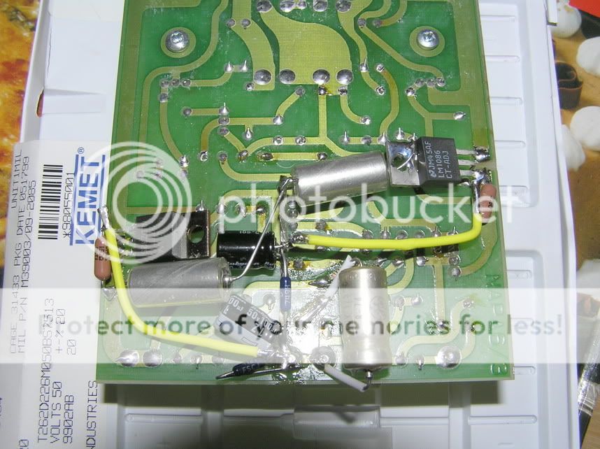
2- Second step- ingredients: -two LM1086 and two LM337
-four 150 ohm resistors (Out-Adj legs)
-four resistors (Adj-Ground), 3300-4500 ohm
according to the desired output regulated
voltage (3300 will give 28.7v and 4500ohm will
give 38.7v,(I chosed 4120ohm for 35.6v).
-four decoupling caps (Out-Gnd) - I chosed
22uF/50v military-grade Kemet Tants (worked
very good for me in several applications-
-four decoupling caps (Adj-Gnd)-
(100uF Rubycon Za/ZL will be fine here).
3- Third step- prepare The victim:
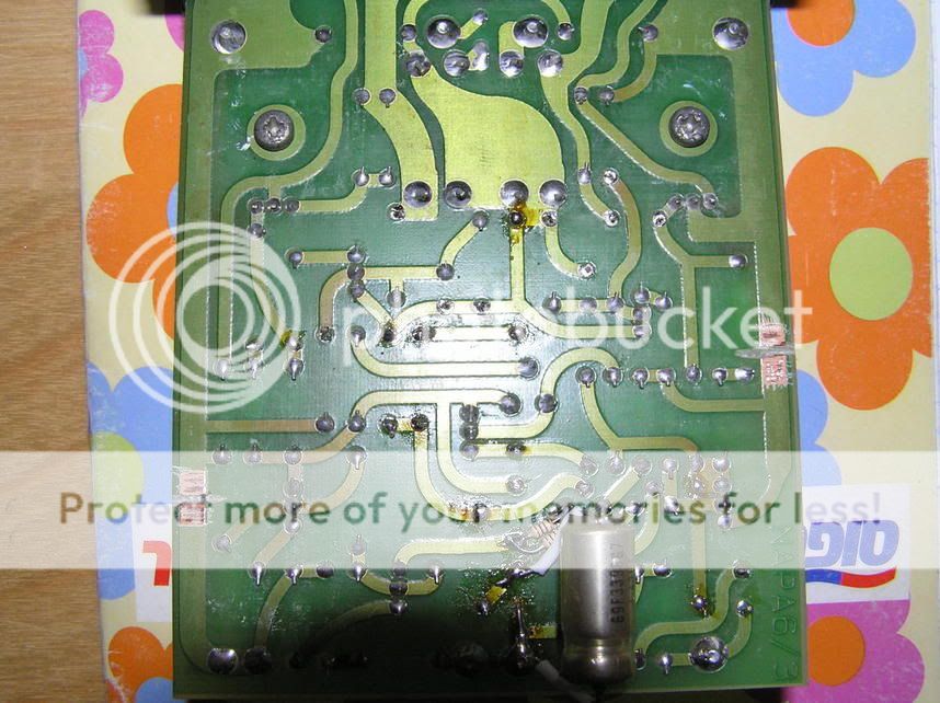
Cut the Nap rails according to the pic (dremel will help in this case).
4- Handwire all the regulators/resistor/caps: (I know it looks messy, But it all beneath the PCB- you can't see nothing above and the connections are with minimum distance)-
5- Check twice that everything is in place, pay attention that you have connected the 317/1086 to the postive rail and 337 to the (-) rail, check caps polarity (337 Adj and Out to (-)!).
6- Turn on voltage for short time, quickly measure the in/out voltages using DVM. Turn on again and remeasure (scope the in/out to see all clean from oscillations- recommended).
7- Increase the NAP idle current to 45mA, check DC offset at the output (speakers disconected!!).
8- Close the amp, put some music and be amazed
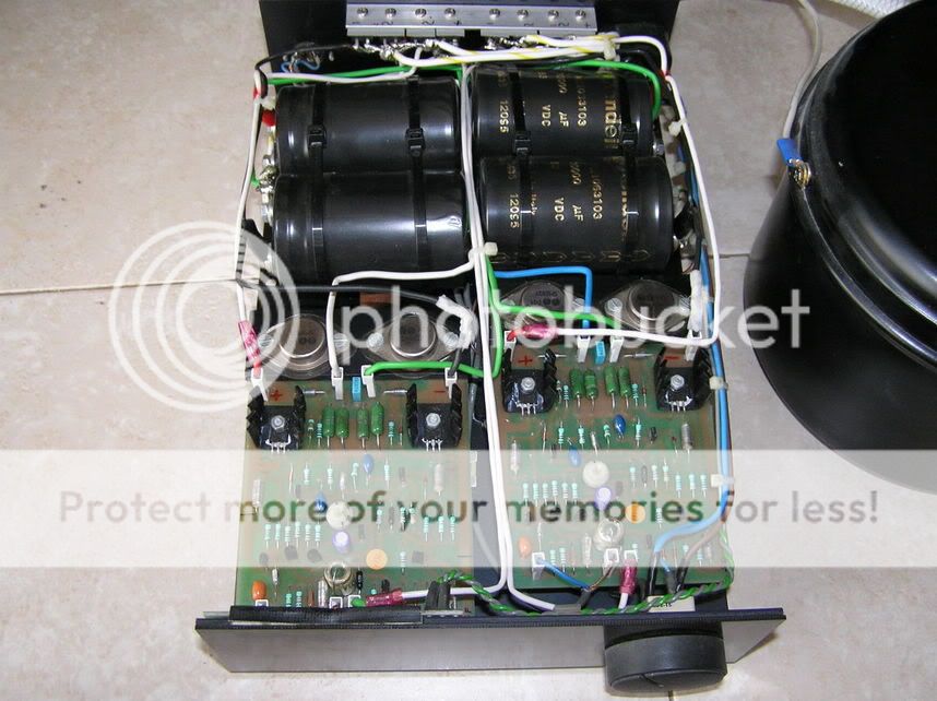
(My "NAP"- An 600VA trafo with 1000VA core lies in a separate round case, Hexfred rectifiers and four 10000uF Kendeils- sorry- no space for 22000uF inside NAP140 case! ).
Cheers,
Avi.
Inspired from Teddy's "NCC Front end regulating" thread (http://www.pinkfishmedia.net/forum/showthread.php?t=20798)
I have implemented the front end regulation in my revised NAP.
The results are superb, It's remindes me the effect of Super regulating my NAC two years ago.
For the benefit of all the "bodgers", Here is the recipe:
1- Open your NAP and measure the voltage on the power supply capacitors-
This should be between 32v to 41v, depends the model (Nap 90 ~32v to
NAP135 ~41v). The Regulated voltage would be set to the rail voltage-5v
2- Second step- ingredients: -two LM1086 and two LM337
-four 150 ohm resistors (Out-Adj legs)
-four resistors (Adj-Ground), 3300-4500 ohm
according to the desired output regulated
voltage (3300 will give 28.7v and 4500ohm will
give 38.7v,(I chosed 4120ohm for 35.6v).
-four decoupling caps (Out-Gnd) - I chosed
22uF/50v military-grade Kemet Tants (worked
very good for me in several applications-
-four decoupling caps (Adj-Gnd)-
(100uF Rubycon Za/ZL will be fine here).
3- Third step- prepare The victim:
Cut the Nap rails according to the pic (dremel will help in this case).
4- Handwire all the regulators/resistor/caps: (I know it looks messy, But it all beneath the PCB- you can't see nothing above and the connections are with minimum distance)-
5- Check twice that everything is in place, pay attention that you have connected the 317/1086 to the postive rail and 337 to the (-) rail, check caps polarity (337 Adj and Out to (-)!).
6- Turn on voltage for short time, quickly measure the in/out voltages using DVM. Turn on again and remeasure (scope the in/out to see all clean from oscillations- recommended).
7- Increase the NAP idle current to 45mA, check DC offset at the output (speakers disconected!!).
8- Close the amp, put some music and be amazed
(My "NAP"- An 600VA trafo with 1000VA core lies in a separate round case, Hexfred rectifiers and four 10000uF Kendeils- sorry- no space for 22000uF inside NAP140 case!
).Cheers,
Avi.