
Arkless Electronics
Trade: Amp design and repairs.
These classic fan heaters are of course a multi purpose utility item and also double as a very good hi fi amplifier and an anchor for boats!
This is an early one of <300 serial number and made in 1983. It belongs to the very lucky Howard, @mandryka of this parish who got it cheap after it had apparently blown up and took out its previous owners speakers....
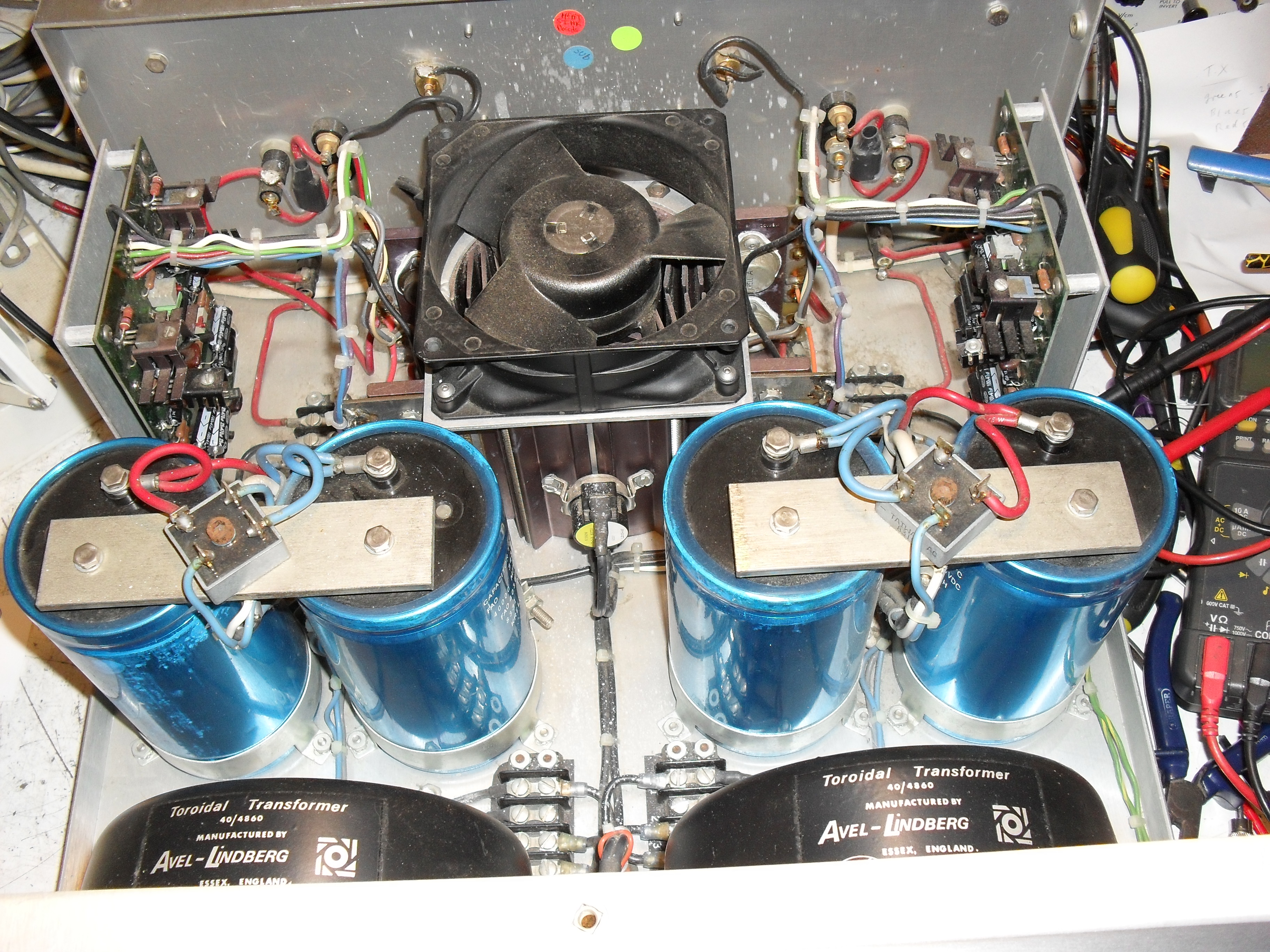
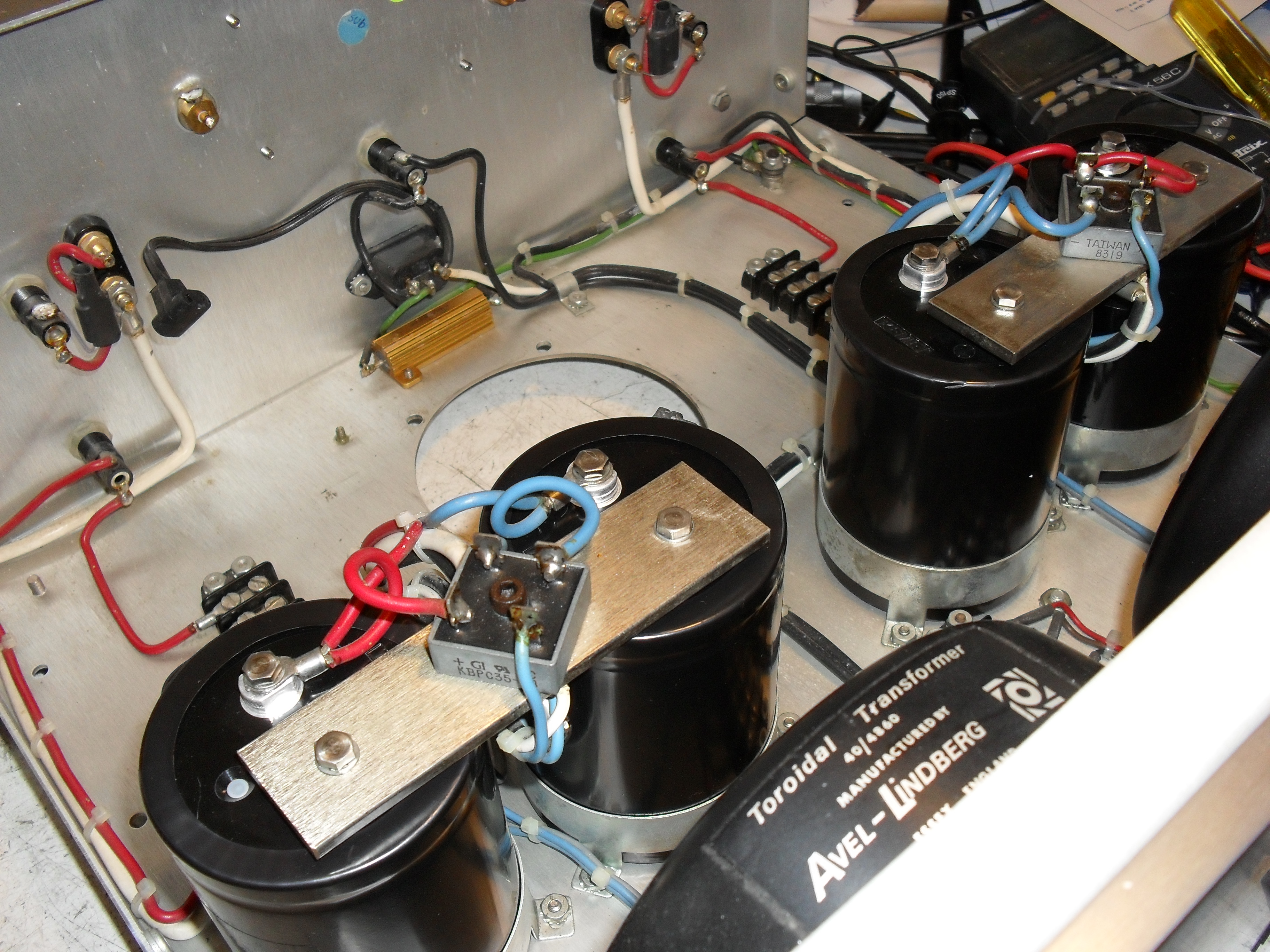
Here it is as received... evidence of some sort of ingress of liquid can be seen against the rear panel. Note British Avel-Lindberg toroidal transformers....
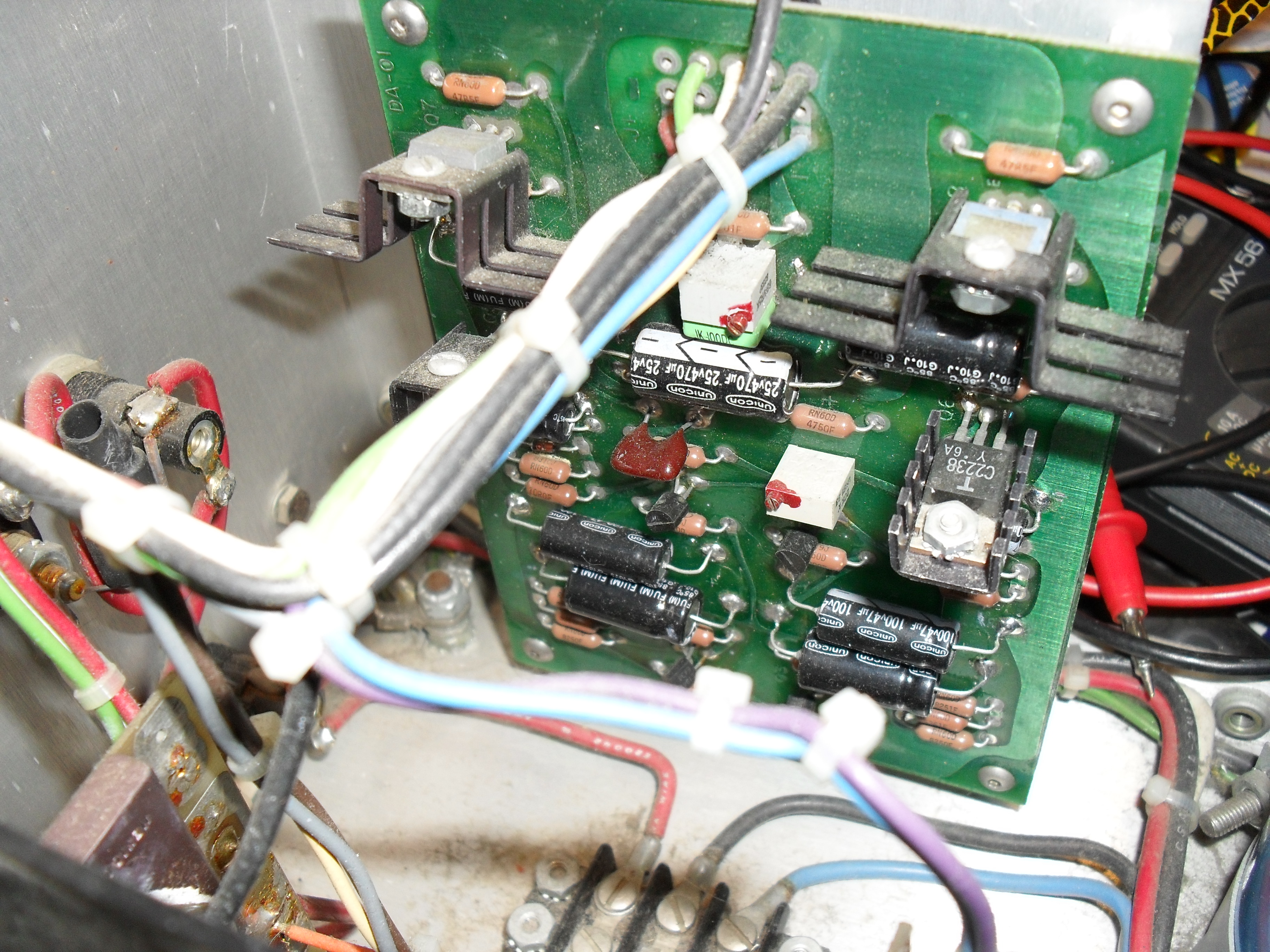
It had been repaired in the past and the bad channel had replacement output transistors fitted, one of which had blown S/C. Electrolytic caps on the PCB's had been changed at some point... badly! Cheapo caps mounted about 1/2" inch off the board as can be seen below and the originals had been cut out rather than desoldered and then the ends bent over flush with the board and soldered over, this made it a nightmare to get the board ready for the new caps and instead of the 20 mins per board it should have took it was more like 2 hours..... The old caps were just butted up to this and soldered.... and one literally fell off when only one end had been desoldered! All were replaced properly with low ESR, long life, 105C rated caps.
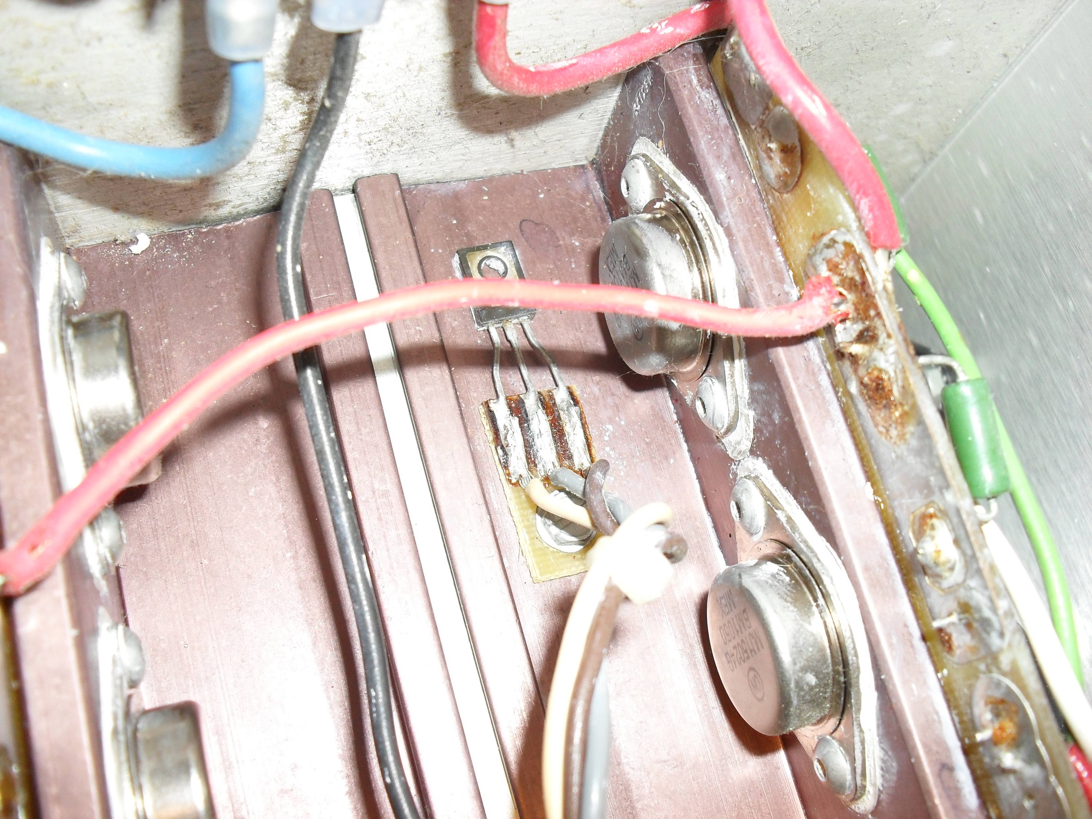
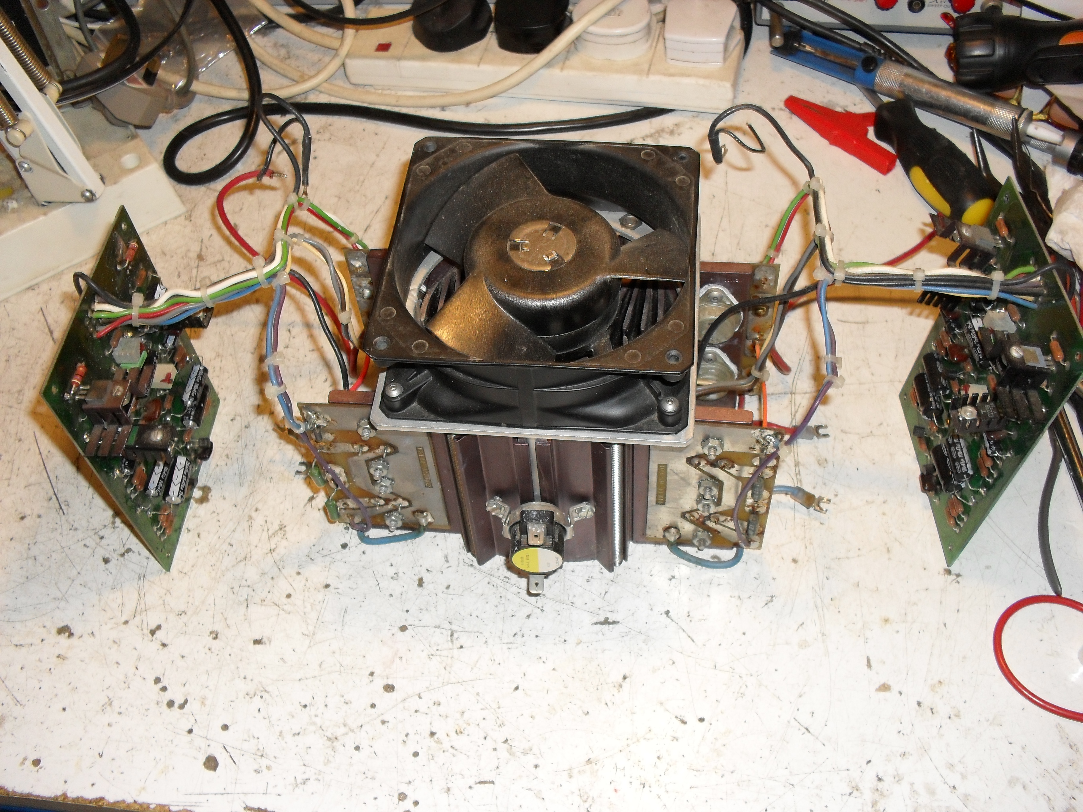
In the image below can be seen the Vbe multiplier transistor (small one with three wires coming from it) which gives thermal feedback and prevents thermal runaway... or should.... The thin film of heatsink paste under these had dried out and on the blown channel there was a fraction of a mm gap between the transistor and the heatsink!
Stripping out of original parts continues....
Removed innards...
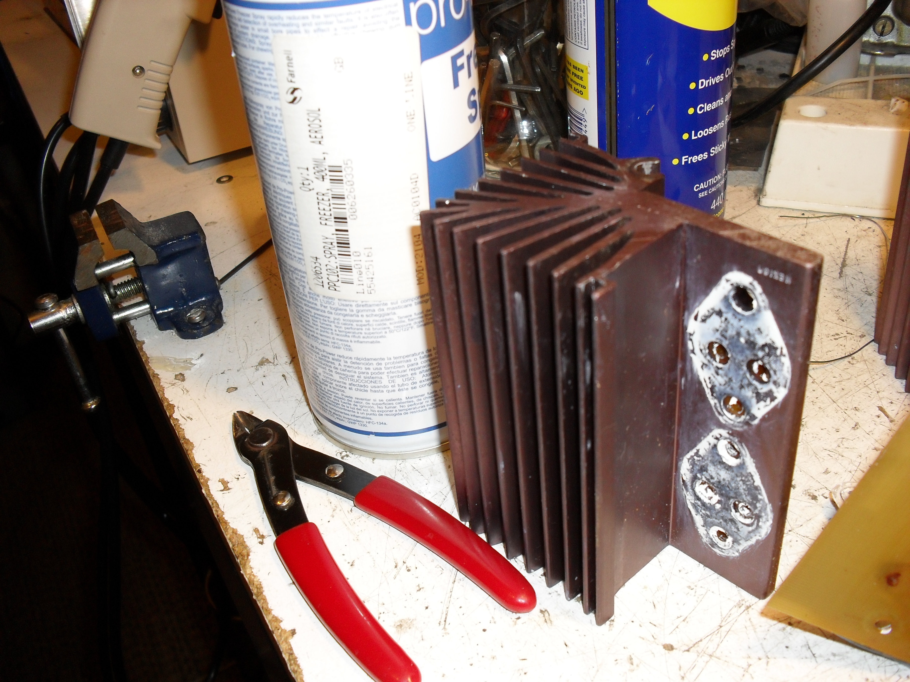
Below is one of the 4 heatsinks before removal of old heatsink compound and dressing of surface for new transistors. A small pair of wire cutters and some aerosols for scale show just how small they can be when forced air cooling is doing the work! They would be good for no more than 10W ish class A without the fan!
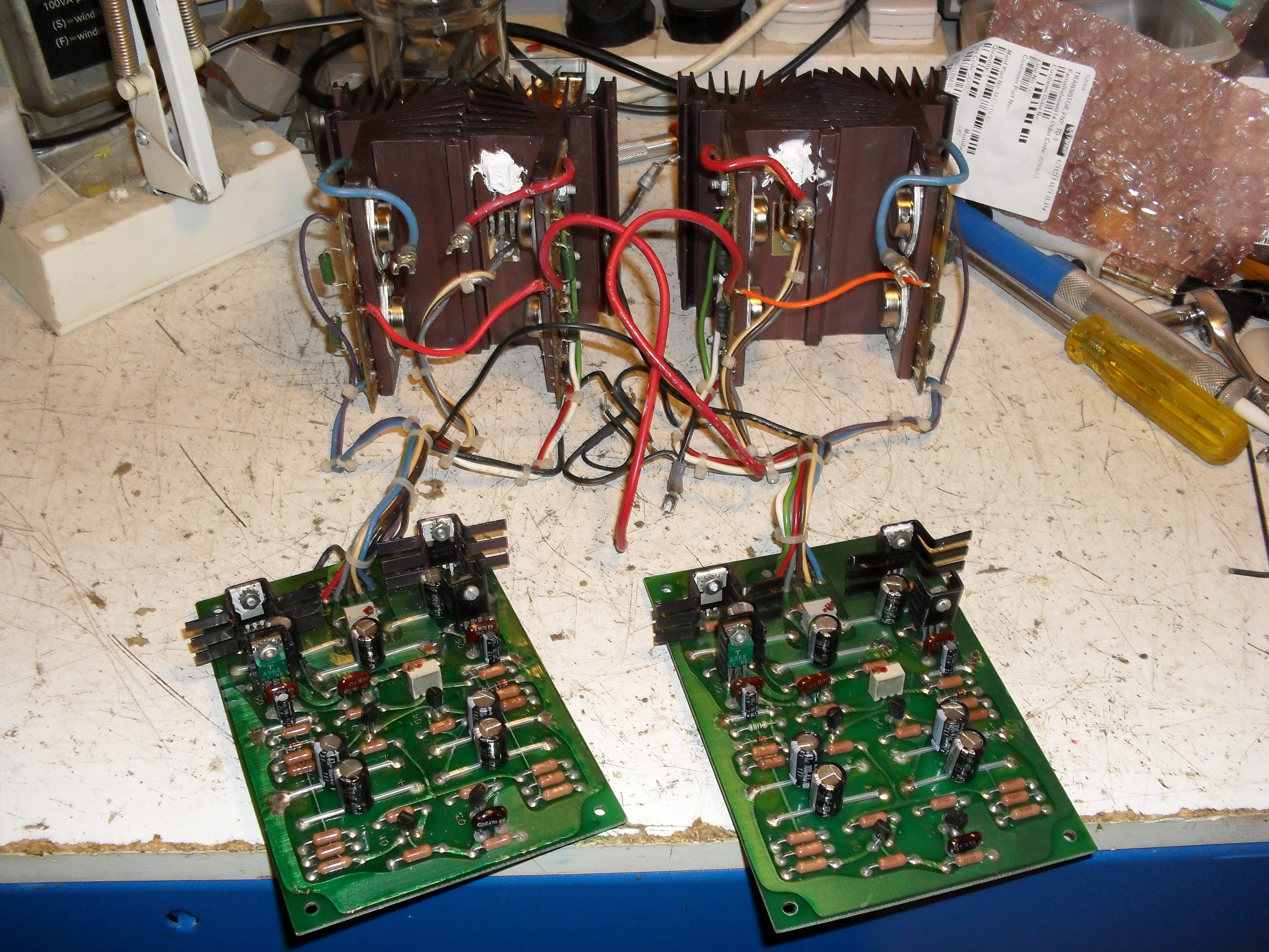
Here are the two channels after having all new electrolytic caps, driver transistors and output transistors fitted. All old transistors and resistors on boards were tested in situ, heatsinks were cleaned off, surfaces dressed, some of the mica insulators replaced, new heatsink compound used and proper thermal contact to Vbe transistors. These were then tested as they are, individually using a bench PSU, and set to a low bias current for now.
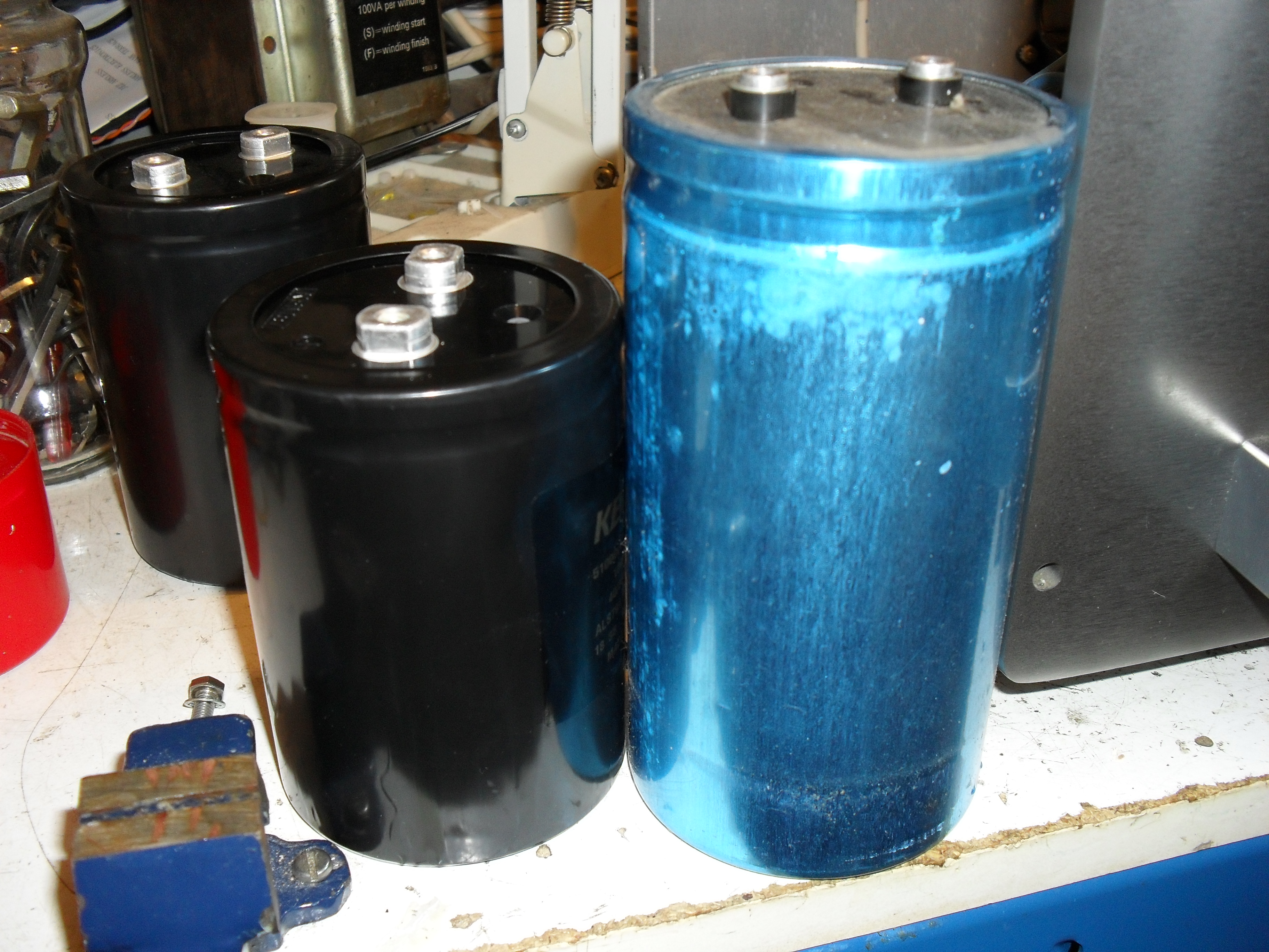
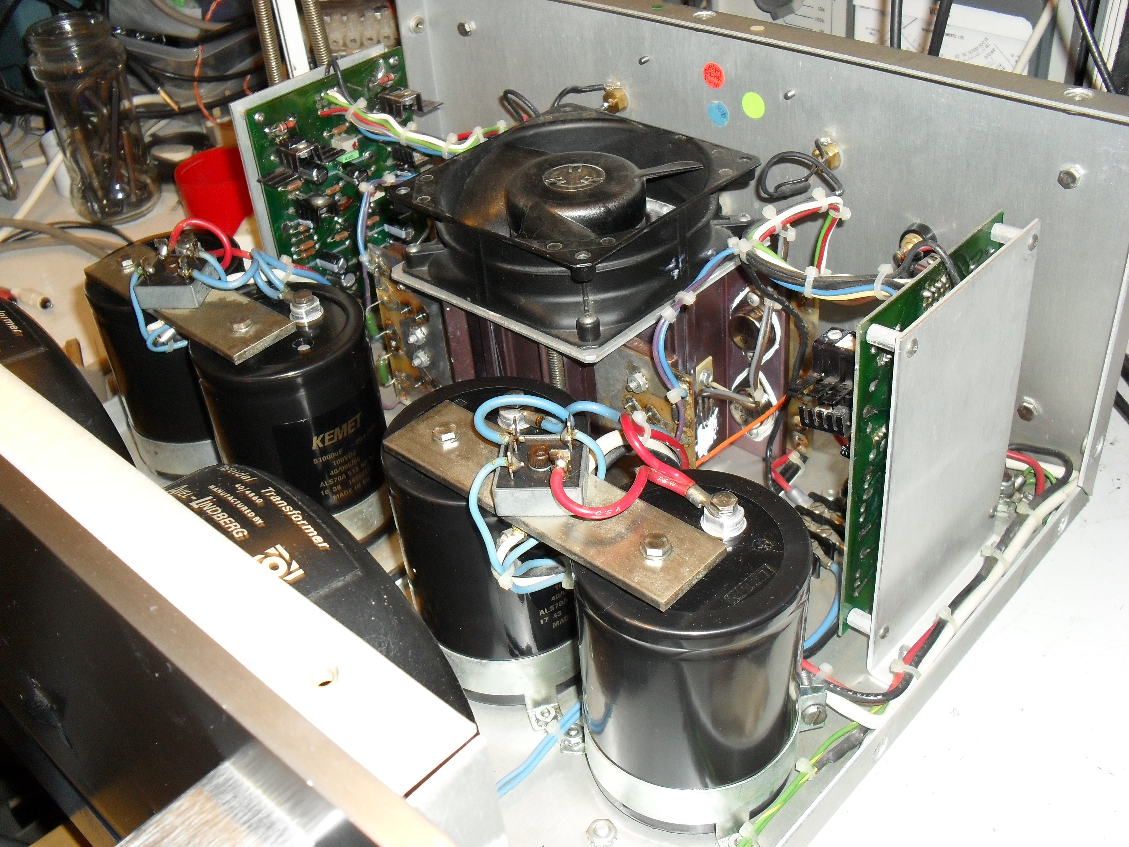
Below is shown one of the original smoothing caps (anyone heard of "Capacitor Technology"? I haven't... also had Krell name on them) next to a replacement for scale... The originals are 40,000uF 75V and the replacements 51,000uF 100V in spite of being smaller than the originals. Originals seemed suspiciously light in weight and the new smaller looking ones are much heavier! A delay was encountered when one of the new ones was found to have a dirty great dent in it and had to go back for replacement...
Getting there...
All done! It was then built up on a large Variac whilst monitoring everything and then when up to 240V settings of class A bias and output offset were carried out (bias had earlier been set low to avoid any surprises of the unpleasant kind at this stage)
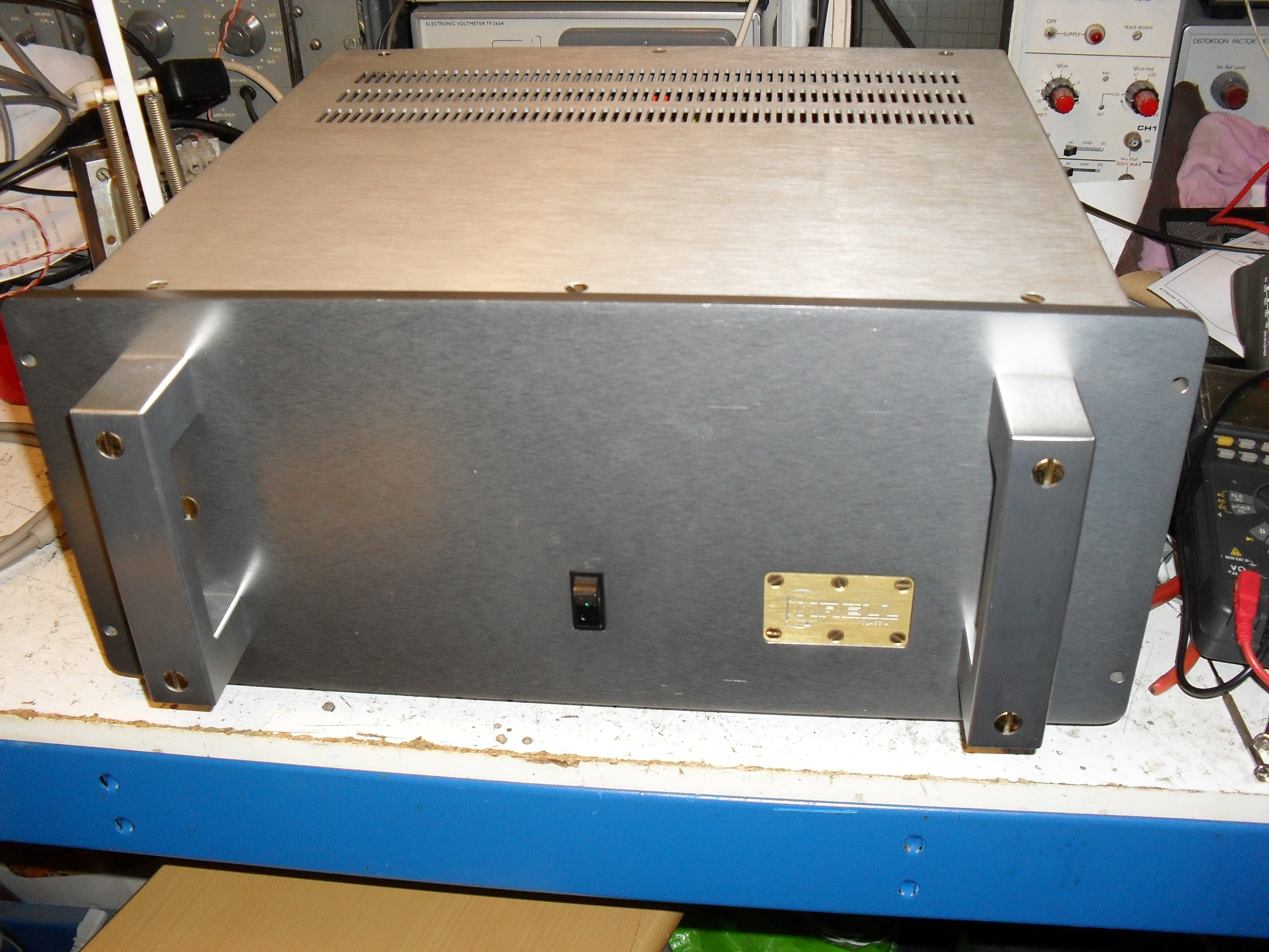
Looking like a Krell KSA50 again!
I had a very pleasant evening listening to it last night and it certainly seemed to get noticeably better even over a few hours as all those new caps burned in!
It has now been on for going on 24 hours with no issues and sounds as wonderful as I had hoped for")
When I opened the door to my living room this morning I though for a second I'd left the heating on.... it does make a good fan heater! It also has a wonderful extra use which not many amps have... when placed on the floor in front of you, you can outstretch your stocking feet and have your feet warmed by the warm air which comes out the bottom of it!
A few days on test and a re-check of bias and offset now before it goes back to its lucky owner
This is an early one of <300 serial number and made in 1983. It belongs to the very lucky Howard, @mandryka of this parish who got it cheap after it had apparently blown up and took out its previous owners speakers....
Here it is as received... evidence of some sort of ingress of liquid can be seen against the rear panel. Note British Avel-Lindberg toroidal transformers....
It had been repaired in the past and the bad channel had replacement output transistors fitted, one of which had blown S/C. Electrolytic caps on the PCB's had been changed at some point... badly! Cheapo caps mounted about 1/2" inch off the board as can be seen below and the originals had been cut out rather than desoldered and then the ends bent over flush with the board and soldered over, this made it a nightmare to get the board ready for the new caps and instead of the 20 mins per board it should have took it was more like 2 hours..... The old caps were just butted up to this and soldered.... and one literally fell off when only one end had been desoldered! All were replaced properly with low ESR, long life, 105C rated caps.
In the image below can be seen the Vbe multiplier transistor (small one with three wires coming from it) which gives thermal feedback and prevents thermal runaway... or should.... The thin film of heatsink paste under these had dried out and on the blown channel there was a fraction of a mm gap between the transistor and the heatsink!
Stripping out of original parts continues....
Removed innards...
Below is one of the 4 heatsinks before removal of old heatsink compound and dressing of surface for new transistors. A small pair of wire cutters and some aerosols for scale show just how small they can be when forced air cooling is doing the work! They would be good for no more than 10W ish class A without the fan!
Here are the two channels after having all new electrolytic caps, driver transistors and output transistors fitted. All old transistors and resistors on boards were tested in situ, heatsinks were cleaned off, surfaces dressed, some of the mica insulators replaced, new heatsink compound used and proper thermal contact to Vbe transistors. These were then tested as they are, individually using a bench PSU, and set to a low bias current for now.
Below is shown one of the original smoothing caps (anyone heard of "Capacitor Technology"? I haven't... also had Krell name on them) next to a replacement for scale... The originals are 40,000uF 75V and the replacements 51,000uF 100V in spite of being smaller than the originals. Originals seemed suspiciously light in weight and the new smaller looking ones are much heavier! A delay was encountered when one of the new ones was found to have a dirty great dent in it and had to go back for replacement...
Getting there...
All done! It was then built up on a large Variac whilst monitoring everything and then when up to 240V settings of class A bias and output offset were carried out (bias had earlier been set low to avoid any surprises of the unpleasant kind at this stage)
Looking like a Krell KSA50 again!
I had a very pleasant evening listening to it last night and it certainly seemed to get noticeably better even over a few hours as all those new caps burned in!
It has now been on for going on 24 hours with no issues and sounds as wonderful as I had hoped for
When I opened the door to my living room this morning I though for a second I'd left the heating on.... it does make a good fan heater! It also has a wonderful extra use which not many amps have... when placed on the floor in front of you, you can outstretch your stocking feet and have your feet warmed by the warm air which comes out the bottom of it!
A few days on test and a re-check of bias and offset now before it goes back to its lucky owner