
Arkless Electronics
Trade: Amp design and repairs.
As promised in the main Radford STA25 thread... and in spite of the memory I have of definitely having posted this before about 2 years ago... It ain't here now!
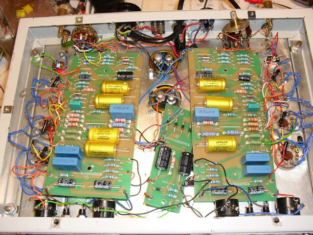
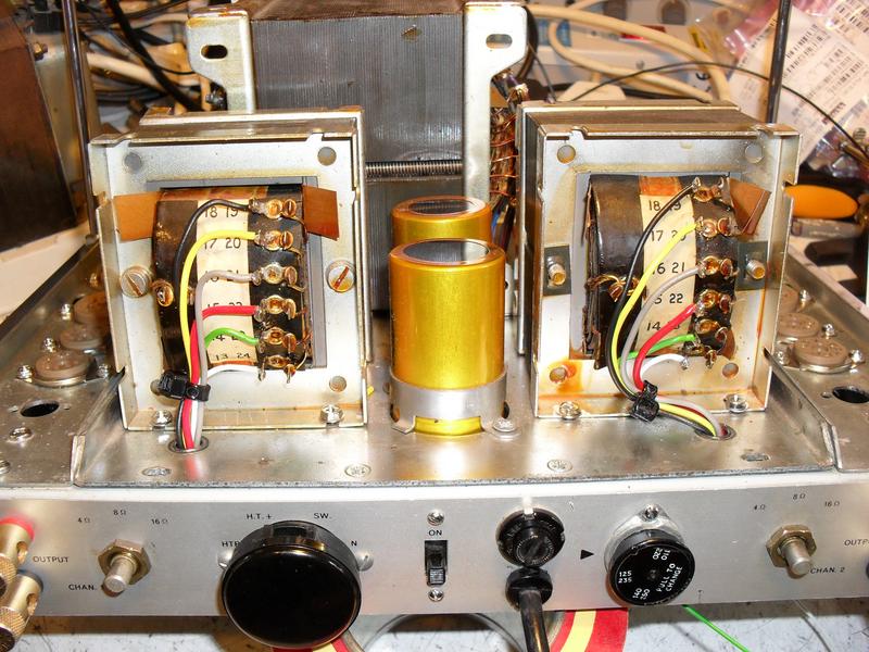
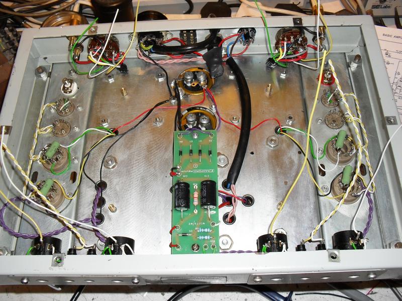
This was it when I received it and had just started to take it apart. It has new boards from Radford Revival but has been messed about with to the extent that it had to be stripped and start again. There are wiring errors and electrolytic caps the wrong way round amongst all sorts of other problems.

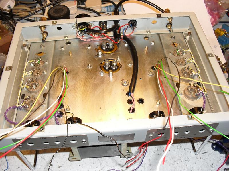
A bit later...
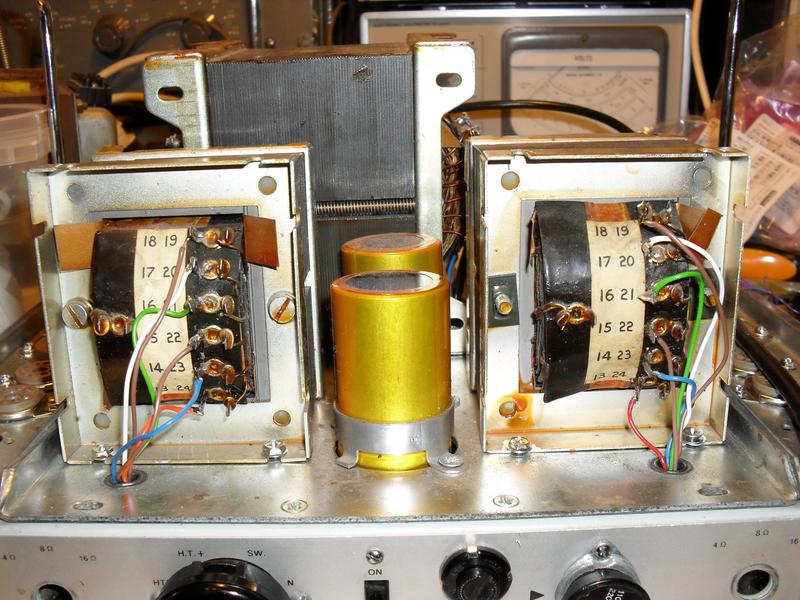
Original wiring to OPT's which had to be re-done.
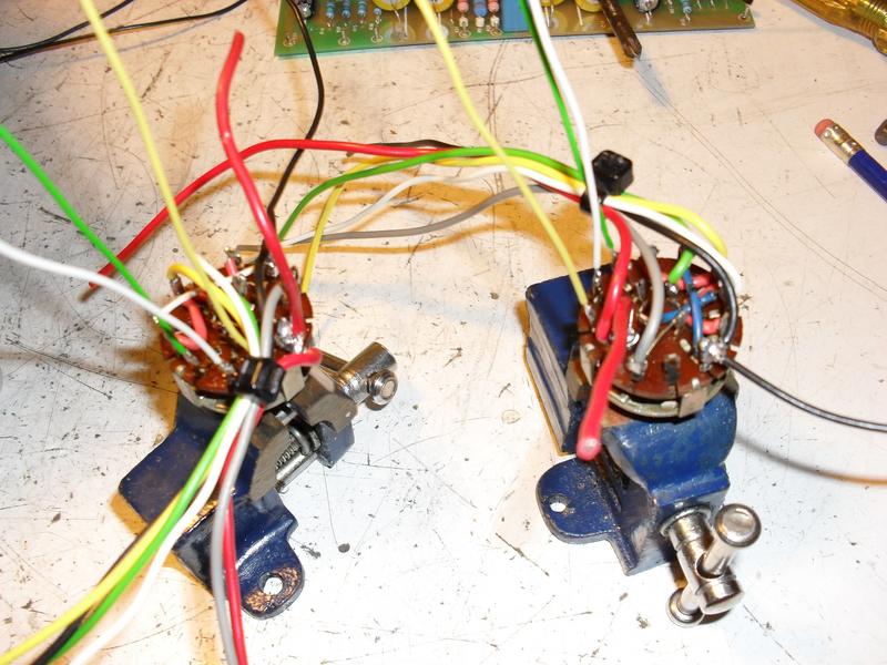
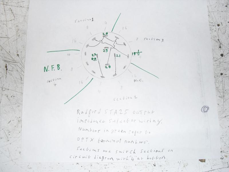
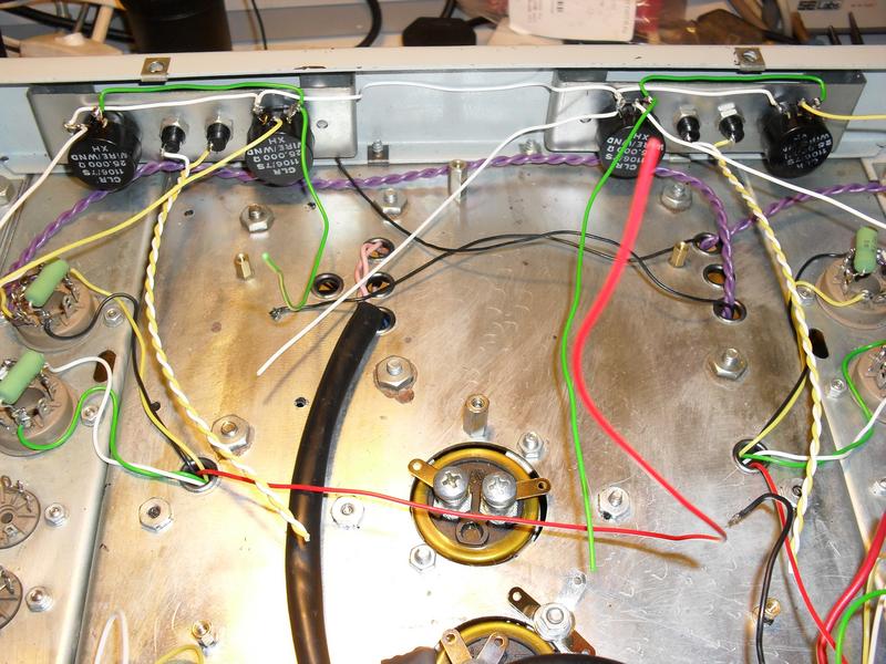
This was a particularly fiddly bit.... rewiring of the speaker impedance switches... unusually complicated as the Radford uses all the windings simultaneously at each setting to give best usage of the available winding area and lowest copper losses etc . It also switches in a different feedback network for each impedance.
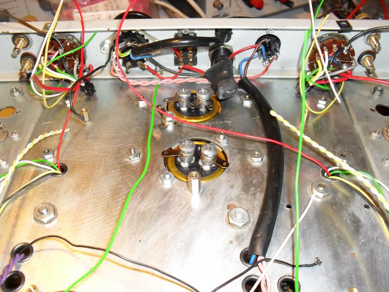
Self explanatory really...
Rewired OPT's
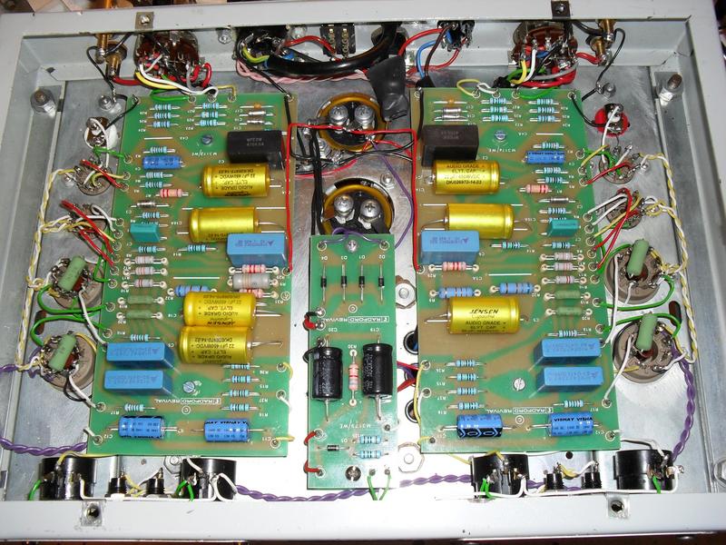
And various stages of reassembly etc culminating in last photo of completed amplifier with various new capacitors, resistors and all board faults repaired plus all rewiring etc completed.
This was it when I received it and had just started to take it apart. It has new boards from Radford Revival but has been messed about with to the extent that it had to be stripped and start again. There are wiring errors and electrolytic caps the wrong way round amongst all sorts of other problems.
A bit later...
Original wiring to OPT's which had to be re-done.
This was a particularly fiddly bit.... rewiring of the speaker impedance switches... unusually complicated as the Radford uses all the windings simultaneously at each setting to give best usage of the available winding area and lowest copper losses etc . It also switches in a different feedback network for each impedance.
Self explanatory really...
Rewired OPT's
And various stages of reassembly etc culminating in last photo of completed amplifier with various new capacitors, resistors and all board faults repaired plus all rewiring etc completed.
