
You are using an out of date browser. It may not display this or other websites correctly.
You should upgrade or use an alternative browser.
You should upgrade or use an alternative browser.
Planet 2000 cdp fix: redux!
- Thread starter The Captain
- Start date
Craig B
Re:trophile
Nah, more a case of 'trawling' (for clearly laid out specific details). Nowt wrong with that.
Or, perhaps a more apropos quote from an anonymous maritimer...
"It is the wise carpenter who measures twice and cuts once."
Or, perhaps a more apropos quote from an anonymous maritimer...
“The good seaman weathers the storm he cannot avoid, and avoids the storm he cannot weather.”
The Captain
~~~~~~~~~~
What @Craig B is saying is that the ribbon in your image post #2 can safely be removed. Once you have the mechanism out and on the bench, you only need to consider the addition of the solder blob before you disconnect the laser circuit from the mech via it's own ribbon cable. If you are simply replacing a sha99ed laser, don't worry about adding a solder blob, just remove the ribbon. When you fit the new laser, insert the ribbon cable and then you are safe to desolder the blob.
I'm not familiar with this particular mech but the shoulders on the fitting in @Craig B's last photo may need lifting to release the laser ribbon cable. Edit: cable is straight pull out / insertion ref below.
This is certainly the case with ribbon connectors on the vam1205 and cdm2 mechs I've worked on.
Fantastic. I'm finally there! Now it makes sense, as how on earth could I get a solder iron in there as it is.. I'd burn the cdp casing. Two ribbon connectors without folks distinguishing between them (&/ or assuming I'm a step further ahead in planning this job) has been the cause of all the confusion.
Right. So first up I've got to physically get my hand in & prize this larger 'main' ribbon cable out. Not easy.
Are these definitely just push-fit? There's no side tiny placcy 'lock' doo-daa's each side you have to press in to release it? Seems a bit scary to me. And they seem fragile too. Hmm..
Nah, more a case of 'trawling' (for clearly laid out specific details). Nowt wrong with that.
"It is the wise carpenter who measures twice and cuts once."
Or, perhaps a more apropos quote from an anonymous maritimer...
“The good seaman weathers the storm he cannot avoid, and avoids the storm he cannot weather.”
Nein, doubt it. Wise carpenters sure measure twice but definitely not quad- or more-uple.
a.palfreyman
pfm Member
Craig B
Re:trophile
This is the d.i.y. room where folk help each other with DIY repairs and projects and/or proudly show off their DIY repairs and projects.Ok, then you all must have much more patience than me ))
I can sort of see where you are coming from, in as much as some of this has been mentioned over in the "Wot CDP rail grease?" thread (which I've only just reviewed, so credit to those, including yourself, who've previously posted similar info).
Regardless, there is no justification for being rude here. This isn't the audio room, nor is this thread about mains cables, foo fuses, and/or audiophile network routers.
martin clark
pinko bodger
@Craig B +1 to all that.
(for everyone else - please Utterly set-aside the OP post from Rory, the Captain - a solid member here for decades - in the comment that follows )
There are really good reasons to support serious repeated enquiry for ' a detail not understood': written words, esp. in inline,-web-post-chat format - are often a really poor ways to communicate in the way we might more clearly face-to-face; and it also does not well-support those - (NONE of this thread, at all, I reiterate) - who might need clarity, or diagrams, or other comparable support for many other reasons 'they' chose to not disclose - from, say, dyslexia and sim through to many other more-personal sight/sense/cognitive issues.
To be generous with a little patience, the time to take a little more care, to make-clearer - is the mark of a welcoming community. It makes the route forward clear for the casual reader, too! I sincerely appreciate that remains a prevailing ethos here.
Oh - and in all the time I've posted here (er, user #10, that's a long time) - I can only think of one, very fleeting timewaster in the DIY section.
Regardless, there is no justification for being rude here. This isn't the audio room, nor is this thread about mains cables, foo fuses, and/or audiophile network routers.
I can't see how my responses was rude, and yes, I'm aware of dysleksy pretty much thank you. And maybe in this case it will better that someone who can manage laser replacement will do it instead of repeating seventh time same thing. I can't because I'm some 1k miles from you all.
a.palfreyman
pfm Member
...sometimes what seems painfully simple to some is complex to others...and even with best intentions, language that makes sense to some doesn't to others. Offset with the fear of possible damage, that misunderstanding becomes multiplied. We all start somewhere.
martin clark
pinko bodger
I can't see how my responses was rude, and yes, I'm aware of dysleksy pretty much thank you. And maybe in this case it will better that someone who can manage laser replacement will do it instead of repeating seventh time same thing. I can't because I'm some 1k miles from you all.
Which means you are reading, and posting, in what might be your second , or third, language - but so far it is not apparent until you told us.
The desire for clarification comes from the little things: just like that
")
ATB!
On that I disagree, there are things that you're good at, and things to leave to others. If you cannot figure out how to unscrew controller board from cd mech to get access to laser optics from numerous posts with pictures then maybe that's not a thing you want to touch. Again "disclaimer", not trying to be rude, I never touch my car more than simple things even blonde can do....sometimes what seems painfully simple to some is complex to others...and even with best intentions, language that makes sense to some doesn't to others. Offset with the fear of possible damage, that misunderstanding becomes multiplied. We all start somewhere.
Craig B
Re:trophile
Pulling the larger 'main' ribbon cable shouldn't require physically getting ones hand in, at least not very far. You simply disconnect it at the mech end as per the service doc entitled 'Changing CD Mechanism'. The mech end ribbon cable socket is along the bottom RH edge of the mech so keeping the mech the right way up and lifting it clear enough from the player lid, and/or simply tilting the RH side up a bit, should give ample access for a clean thumb and finger pull straight out. Note: you are not pulling the plastic connector, simply pinch the ribbon between your fingers at the blue insulation and pull nice and even, straight out.Fantastic. I'm finally there! Now it makes sense, as how on earth could I get a solder iron in there as it is.. I'd burn the cdp casing. Two ribbon connectors without folks distinguishing between them (&/ or assuming I'm a step further ahead in planning this job) has been the cause of all the confusion.
Right. So first up I've got to physically get my hand in & prize this larger 'main' ribbon cable out. Not easy.
Are these definitely just push-fit? There's no side tiny placcy 'lock' doo-daa's each side you have to press in to release it? Seems a bit scary to me. And they seem fragile too. Hmm..
To summarize the service docs that were sent (and starting from where you are now with mech and CD tray assembly detached from player via removal of 2 x small hex screws)...
- Disconnect large ribbon cable that connects from main CD player PCB to mech at mech end.
- Place mech and CD tray assembly upside down on RH side of player (a rubber mouse pad as buffer here is good)
- Remove mech from the CD tray via removal of 4 x screws. The other wires that connect to the lid sensor on the CD tray can be left in place as there is sufficient slack to leave the tray sitting atop the player once the mech is separated from the tray. Note: It is only once the mech is separated from the CD tray that the optical block can be removed.
- Unclip and slide the metal running bar out from the optical block and mech chassis guides.
- Lift optical block up and out from the mech just enough to unplug the small ribbon cable that connects between optical block and mech PCB (unplug at the optical block end as per the sequence of photos and steps in the second service doc).
The service docs assume reversing the take apart procedure, however, to be specific:
- Reconnect the small ribbon cable from mech to optical block (then remove the alligator clip if used).
- Locate the optical block back into the mech, and reinsert the metal running bar until it locks into place.
- Reattach mech to CD tray via the 4 x screws and washers (don't over tighten as this can cause disc skipping).
- Reconnect large ribbon cable to mech.
- Position mech/CD tray assembly back into player lid and secure via 2 x small hex screws.
Last edited:
The Captain
~~~~~~~~~~
This is the d.i.y. room where folk help each other with DIY repairs and projects and/or proudly show off their DIY repairs and projects.
I can sort of see where you are coming from, in as much as some of this has been mentioned over in the "Wot CDP rail grease?" thread (which I've only just reviewed, so credit to those, including yourself, who've previously posted similar info).
Regardless, there is no justification for being rude here. This isn't the audio room, nor is this thread about mains cables, foo fuses, and/or audiophile network routers.
Hi chaps, been so busy I'm only getting round to untethering the main cable later. Thanks so much for the replies, & patience; To those in the know, the other thread will likely have the same info as here. Yes. But that thread simply wasn't clear -to me- (one reason being: language used). You could likely see through the language issues/ see what X was attempting to explain.. but to me it just meant that the confusion grew & grew. And I had to stop.
Now Im on board- I'm away. And just need to ask simple steps, via a few lines of spiel only. Pics I know how too now.
Will update on condition of rail later assuming I get ribbon done & transport out: the fallible rail being the placcy flat one it seems. My focus 1st up is here, as ansis suggested.
Thanks, Capt
The Captain
~~~~~~~~~~
Aye, aye, Captain, still onboard here. Will answer questions with short and clear replies as they come in from the bridge, going forward.
Steady as she goes! (steady as she goes) [cue sound of foghorn in distance].
[Fab step by steps above CraigB.. just what I need].
Right me hearties, got me cable out ( not possible without a twist mind you, hmm..).
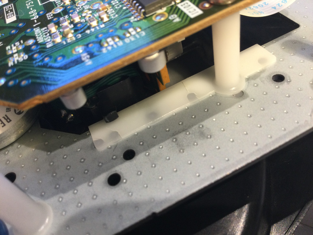
If I can refer back to ansis' advice on the other thread at this point; I see how the optical block travels along via two rails, a main metal one & a much thinner plastic 'guide' rail. This placcy one ansis said " look for cracks ".
Could this be what he means: do thee seem like a cracks? One in the middle & also one to the LHS end (closest to camera). Perpendicular, across the 10mm width..
Craig B
Re:trophile
I wouldn't worry about the crack down far left, as the optical block only travels as far inward (toward the centre of the CD) as roughly where it is now.
That middle crack concerns me more. Zooming in on the photo suggests a slight change in elevation, however, I'd be wanting to get the CD tray off and have a closer look at the other side (as the mech is upside down, and therefore, gravity won't necessarily have the black guide tab at quite the same tension against this side of the plastic rail as it might the other side, IYSWIM).
Regardless, I'd still proceed with a clean and lube, perhaps running any bump along the plastic rail down with a bit of emory cloth on a finger.
The Captain
~~~~~~~~~~
I wouldn't worry about the crack down far left, as the optical block only travels as far inward (toward the centre of the CD) as roughly where it is now.
That middle crack concerns me more. Zooming in on the photo suggests a slight change in elevation, however, I'd be wanting to get the CD tray off and have a closer look at the other side (as the mech is upside down, and therefore, gravity won't necessarily have the black guide tab at quite the same tension against this side of the plastic rail as it might the other side, IYSWIM).
Regardless, I'd still proceed with a clean and lube, perhaps running any bump along the plastic rail down with a bit of emory cloth on a finger.
Understand all that- yes I see why the LHS crack is n/a now, good. How can such cracks even happen though? And could I replace just this rail I wonder.. ideally so & take block off, lube it all, put back together & evaluate.
I was also wondering too if, as you allude to, the rail could be 'repaired' by filling or joining or summink, ie with some cunning & careful diy.
[Rather good trawling pun too Admiral Craig- spot on that].
Craig B
Re:trophile
Dunno, perhaps it's all that salt air?Understand all that- yes I see why the LHS crack is n/a now, good. How can such cracks even happen though? And could I replace just this rail I wonder.. ideally so & take block off, lube it all, put back together & evaluate.
I was also wondering too if, as you allude to, the rail could be 'repaired' by filling or joining or summink, ie with some cunning & careful diy.
[Rather good trawling pun too Admiral Craig- spot on that].
Judging by looking at the top side of the full Sony mech pictured within the second service doc, I'd not expect these nylon mouldings to be much different on the mech that came in Planet 2000. Bit of a multi-function piece that serves more than the one purpose, therefore, not easily replaced, let alone being highly unlikely to be available as spare part. This is the primary reason why I suggested trying emory cloth to take down any bumps should they prove to be something that you can feel by running your finger along (i.e. feel both sides once you have the plastic CD tray off). IOW, I don't see fine hairline gaps being so much of an issue as bumps might be.
a.palfreyman
pfm Member
Definitely a crack. As @Craig B sez, there is a visible step. If you can feel it with a fingernail passed over it, it is significant. IPA and a toothbrush to clean it. Let it dry thoroughly. Spot of gel super glue wicked into it and leave overnight. Some fine sandpaper / emery cloth to dress it which you should slide along the rail rather than across so any minor grooves won't matter.