
You are using an out of date browser. It may not display this or other websites correctly.
You should upgrade or use an alternative browser.
You should upgrade or use an alternative browser.
PCB track shapes?
- Thread starter bugbear
- Start date
JensenHealey
pfm Member
Tip #6 – Avoid Using 90 Degree Trace Angles
You’ll hear this time and time again if you talk to engineers and manufacturers, don’t use 90-degree trace angles. Why? When you have a bunch of traces that have a sharp, right angle turn on your board, the outside corner of that 90-degree angle has the likelihood of being etched narrower than your standard trace width. And at its worst, you might get a bunch of 90-degree traces back that aren’t fully etched, resulting in shorts.

Avoid using 90-degree trace angles, opt for 45 degrees, with a smooth angle being the best.
As a solution to this problem, try to use 45-degree angle traces. This will produce some beautiful PCB layouts while also making your manufacturer’s life easier by being able to easily etch away all of the copper on your board.
You’ll hear this time and time again if you talk to engineers and manufacturers, don’t use 90-degree trace angles. Why? When you have a bunch of traces that have a sharp, right angle turn on your board, the outside corner of that 90-degree angle has the likelihood of being etched narrower than your standard trace width. And at its worst, you might get a bunch of 90-degree traces back that aren’t fully etched, resulting in shorts.
Avoid using 90-degree trace angles, opt for 45 degrees, with a smooth angle being the best.
As a solution to this problem, try to use 45-degree angle traces. This will produce some beautiful PCB layouts while also making your manufacturer’s life easier by being able to easily etch away all of the copper on your board.
davidsrsb
pfm Member
The old 90 degree etching theory is rarely a real problem. Back in the tape days the 90 bend meant overlapping two tapes and that could be bodged.
These days 45 degree corners are used because it makes tracks shorter and use less board area.
Reflections at the corners are not detectable below a few GHz.
These days 45 degree corners are used because it makes tracks shorter and use less board area.
Reflections at the corners are not detectable below a few GHz.
Arkless Electronics
Trade: Amp design and repairs.
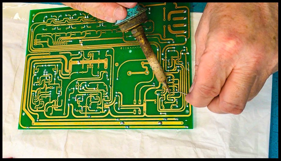
Are the beautiful arched tracks on this Board "best practice" or an affectation?
BugBear
More an irrelevance really!
Barrymagrec
pfm Member
I still have a drawer full of various width black PCB tapes and holes - should chuck them really, no use these days and so old they probably wouldn`t stick anyway.
JemHayward
pfm Member
A friend of mine who used to design and build medical electronics siad that he used curved traces to avoid 'aerial' effects and RFI issues. Not sure if that is true, but his wasn't into hifi so didn't know anything about foo.
Arkless Electronics
Trade: Amp design and repairs.
A friend of mine who used to design and build medical electronics siad that he used curved traces to avoid 'aerial' effects and RFI issues. Not sure if that is true, but his wasn't into hifi so didn't know anything about foo.
Not applicable to audio frequencies. At UHF and above some care must be taken as tracks are often designed for a constant impedance (track width and PCB dielectric constant and sometimes thickness of PCB to ground plane on other side set the impedance. "Micro-Strip" and "Strip-Line") and care must be taken in corners to keep constant impedance and keep reflections down.
JemHayward
pfm Member
That make sense, though his stuff wasn't (as far as I know) high frequency based, though it was using crystal oscillators for timing and precise measurements of stuff, so maybe he was using curved traces as 'best practice'.
Arkless Electronics
Trade: Amp design and repairs.
Shush, the foo believers will be planning special pens to draw rounded corners on all the tracks.... which they will report as making a night and day difference... even with their probably out of phase speakers!
m3trackboy
pfm Member
I've put little barriers from scalectric to keep the electrons from over shooting the corners
Andrew L Weekes
Reverse Engineer
The old 90 degree etching theory is rarely a real problem. Back in the tape days the 90 bend meant overlapping two tapes and that could be bodged.
These days 45 degree corners are used because it makes tracks shorter and use less board area.
Reflections at the corners are not detectable below a few GHz.
Yes, this.
45 degree corners look nicer and I'll always use them for aesthetic reasons, but they aren't a necessity. At RF frequencies the corners of right angles are mitred to keep trace impedances constant in microstrip designs, e.g. https://www.everythingrf.com/rf-calculators/microstrip-mitred-bend-calculator.
There's also no harm in making the board manufacturing process more robust, and less likely to have issues especially where density isn't a big issue, but PCB manufacture has improved a lot with the advent of tighter design rules and higher component densities.
russel
./_dazed_and_confused
I design PCBs in radios and with high speed digital. The only thing wrong with right angle bends below 1 GHz is that the track is much longer than it needs to be and therefore wastes space.
Some people think of electrons like cars on a race track, having to slow on corners
Return path currents cause a lot of EMC issues, so a lot of right angles are best avoided, plus they start looking like antennas and can pick up rubbish, again EMC.