advertisement


Old Class A /B 45 watt amp kit

Col

pfm Member
Hi All
Well I am interested to know if anyone knows or built this Class A. /B 45 watt amp kit amp Designed by Graham Nalty know of black widow cables

I have all the PCBs Plus build and upgrade Manuals of the Day for this separate Pre/Power Amp combo, which I still have not built as went in a different direction with my Hi Fi i will have to lookin to building this think some winter nights soon :)

Both pre/ power amp use lots of Voltage Regs
The Amp was give good review by Martin Colloms of Hi Fi Answers I Think at the time

The Apex Amp Schematic

And overlay

 
It uses lots of cascodes, without base stoppers. I expect it oscillates at 10s of MHz.

The triples in the output stage are "double darlington" layout which wastes voltage rail, and gives extra poles in the stability analysis.

There is no output device protection, so be very careful to not short anything.

Definitely want scope, signal generator and dummy load for setting this one up, to check for HF/VHF oscillation.
 
I built one of these and still have the completed boards. I wasn't impressed by the sound at the time and it was bettered by my NAD 3020, possibly because of the aforementioned oscillation, although I had no means to measure it back then. I subsequently modified the output stage, removing the darlington pre drivers and replacing these with 2N6553/6 devices. At the same time I changed it to a quasi complementary and used a pair of BDY58's for Tr15 and 16 copying the Naim design. That improved the sound a lot. I also put a 10uF tantalum across TR11 C-E and the aforementioned base stoppers on the cascode transistors.

After all that the board looked a bit of a mess but it sounded OK. For its time the separate regulated feeds to the front end and the caps near to the output stage were quite radical and an improvement although the use of film caps where a bit of ESR is actually beneficial on the regulators limited the gains to the design. The Hackernap is a whole lot better IMHO.

John
 
Thanks for the lowdown on this Apex Amp
Was interested to see if anyone here had built it.

I don’t think I will bother with it now seems like it will be to much trouble to get right plus I don’t have a scope or the knowhow

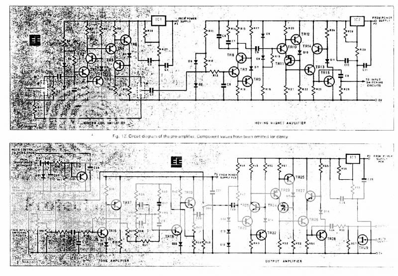
John did you build the pre amp and phono I may still consider the pre and phono stages less the tone circuit more cascades but would value your views over the pre/phono circuit see Schematic
Apex Pre/Phono Schematic

 
If you are after a pre, build the B4.. Its a seriously good bit of kit.

Ah yes I have read some of the B4 thread on here looks interesting only problem seem to be hard to get parts i.e. the 1N5287/5297 from UK suppliers

But if there’s a common replacement for these parts I would be interested in getting the PCB if still available on Here
 
I have been thinking of a thread on the whereabouts of Graham Nalty since I recommissioned a preamp he designed as Audiokits for my office system. The original design was for one of the monthly mags -- an integrated amp as the OP stated -- with passive equalisation in the phono section using three descrete "op amps" followed by a similar stage as the output buffer. At the time this piqued my interest and Graham was prepared to part a circuit board, supply the parts and a design for a power supply. With a MM system running I contacted him regarding an MC input and he designed a new stage and power supply with a lower voltage 1st stage and supplied all the parts. I ran this until I went "flat earth" and passed it on to my father-in-law who was an old school valve man and stuck it in the loft following a power supply failure. We found it when clearing the house, stuck a new transformer and regulator in one of the channels and hey presto music! I believe it makes a major contribution to the open sound and sound-stage I get in my system running either vinyl from an old Sansui deck (also found in the loft) or digital via Raspbery Pi/Maplin DAC.
If anyone's interested in circuit diagrams etc I think I have them stashed away in a cupboard somewhere.
Steve
 
The triples in the output stage are "double darlington" layout which wastes voltage rail, and gives extra poles in the stability analysis.

Excellent point.

I think this configuration was a consequence of NPN transistors still being expensive for PNP/NPN pairs back in seventies. That's no longer true, so one could use more modern pairings.

There is no output device protection, so be very careful to not short anything.

True and important. No sense frying expensive transistors when an inexpensive protection circuit works. Beyond that, the circuit lacks protection against DC output which would fry the speakers, and that's very important.
 
It uses lots of cascodes, without base stoppers. I expect it oscillates at 10s of MHz.

What base stoppers would those be?

I have seen a lot of cascodes, and the only requirement seems to be that the joined bases be polarized to V+ (V-) and to ground, with two resistors, or one resistor and zener or diode or LED.

The power amp cascodes seem to fulfill that. What is missing?
 
Thanks for the lowdown on this Apex Amp
Was interested to see if anyone here had built it.

I don’t think I will bother with it now seems like it will be to much trouble to get right plus I don’t have a scope or the knowhow

John did you build the pre amp and phono I may still consider the pre and phono stages less the tone circuit more cascades but would value your views over the pre/phono circuit see Schematic
Apex Pre/Phono Schematic


Blimey, blast from the past. I buit one of those preamps. I saw the gain block as a Naim circuit with sort of bootstrapped cascde added. I seem to remember NE5534s sounding better.

Nalty when on to be a cable guru, can't remember the brand but seem to remember rubber insulation was the USP.

"Nutty Nalty" was how one hifi designer referred to him.
 
I built two Apex power amps, and they both sounded very very good.

I got to compare them to others, and the Nalty was always the best.

One I gave to a friend, and then built another one, that used for several years. Blew an output transistor on one channel, but fortunately didn't blow the woofer.

You have to use good parts on it.

Before that I also built two Nalty MM preamps, one single sided, like the Apex preamp, and a dual supply design published in ETI. The single sided sounded better.

Recently I discovered that a similar design to his power amp, minus the Darlington drivers, is used by the Classe 15 power amp. An AB amp. More powerful, but with similar stages. I can put the schematic here if you want it.
 
What base stoppers would those be?

I have seen a lot of cascodes, and the only requirement seems to be that the joined bases be polarized to V+ (V-) and to ground, with two resistors, or one resistor and zener or diode or LED.

The power amp cascodes seem to fulfill that. What is missing?

You normally want a 100Ohms (or thereabouts) resistor in series with the base, to introduce some high frequency damping. If you don't have base stoppers, the very high bandwidth of cascode stages makes it very easy to get oscillation at 10s of MHz, which can be hard to diagnose and inconsistent.
 
Good catch, it should have base stoppers on the cascodes on the LTP too!

Actually, the VAS doesn't use cascodes - it has an emitter follower buffer (Q12, loaded by current source Q13), before the main VAS at Q4.

It also doesn't use the output stage triples, and uses nested feedback and pole zero compensation, so avoiding some of the stability issues.
 
I built the passive RIAA preamp - no op amps in mine, it was fully discrete, and worked really rather well. It compared favourably with the Meridian 103, and I partnered it with a Nytech 602 power amp for some time. The RIAA stage in the Nait 1 was the first thing to beat it, though I briefly went back to it when I was moving into Naim pre-power setups, but I then went to MC so it was retired. I never heard his power amp designs though. He moved into cables with "Black Rhodium" which I think were neither black, nor rhodium, but I imagine were more profitable. No idea where he is now, must be getting on a bit, if he's still with us at all. Seemed to be a really nice chap judging by how he dealt with some pretty daft questions on the phone whilst I was building the preamp.
 
Yes, Graham Nalty is still around, and apparently doing well with some new connectors types.

He helped me quite a lot at the time I was building his designs. I built a simpler, non-cascode MM preamp that was published in Practical Electronics. On it I remember there was a remarkable improvement when replacing the 7815 regulators for LM317, which the Apex already had.

Now, Pigletsdad, let me insist on the cascode base stoppers question. Is there any place I can find info on that?

I say it because I looked at every commercial amp that I have a schematic of that uses a cascode and NONE of them uses such a thing. They just bias the joint bases and that's all.

An you are right that that amp of other thread didn't use a cascode on the second stage.

I can put it here at least three amps that I found with no cascode base stoppers, designs considered good sounding ones.
 
See https://www.researchgate.net/publication/260666067_Stability_in_Small_Signal_Common_Base_Amplifiers
for analysis.

Base stoppers are not always needed, but it depends on details of layout and surrounding circuit - the problem is inductance in the base network (including inside the package) resonating with feedback parasitic capacitance and forming a Colpitts oscillator. Resistor damps this.

Oscillations can be at frequencies over 100MHz, as common base has gain all the way to fT, so hard to measure unless you have a much faster scope than I do!
 
Well, to start with thank you for mentioning this fact and tell me where to look for info about it.

Second, I imagine adding 100R on each base and join them for biasing as usual shouldn't be complicated at all. It might be hard to add it to an existing design, but not that much.

Third, I wonder if we should worry about something happening over 100MHz. And maybe that is the reason why designers do not worry about it.

It's a pity nobody seems to have built that amplifier I mentioned. It's always good to see new designs (for me) and check how they measure or sound. Particularly those not carrying any exotic hard to find parts.
 
Third, I wonder if we should worry about something happening over 100MHz. And maybe that is the reason why designers do not worry about it.

The paper has a discussion of the effects of VHF oscillations on lower bandwidth signals. The problem is rectification - the oscillations vary with operating point, and may well not be sinusoidal. You can also get nasty mixing effects if there is RF interference.
 
I thought that Mouser had good UK delivery options? And I do have a few B4 boards left...
Ah yes I have read some of the B4 thread on here looks interesting only problem seem to be hard to get parts i.e. the 1N5287/5297 from UK suppliers

But if there’s a common replacement for these parts I would be interested in getting the PCB if still available on Here


advertisement


Back
Top