advertisement


Nytech Audio / Ion Systems Appreciation Thread

A Thread resurrection - Hi Guys

I brought the Nytech CTA 252 XD its working but its only playing in MONO on CD MONO switch is Off and tried different cables which are fine with my Quad amps Tried a different link adapter and its still the same a rather odd problem unless someone has wired it for MONO only
17428.gif


Any help would be much appreciated i would love to get this unit going but it was not cheap to start with no i can't get a refund as i tested it and said it was OK..

Help would be much appreciated
 
Hi Bob

I have contacted Nytech and i awaiting a response - Somebody has said the headphone jack trick but i only have one jack at present do i need 2 to cancel it out - another suggestion is a faulty channel this could be true as when the balance is altered to the right it follows to the right speaker but when altered to left it stays the same as if in MONO - I have no idea where the fuses are to see if this is the fault

I'm still hopeing for some advice and i can fix it myself...
 
There are 2 sorts of CTA 252 one with 3 pairs of DIN output sockets and one with 4mm (and 2 pairs of DIN) output sockets.
Either way if you plug your speakers into the 'Direct' sockets the headphones should not (normally) have any muting effect. (SP1 / SP2 not pressed).

You could decide if the Power amp or pre-amp sections are functioning though.
Remove the pre/power link and plug a normal DIN lead in there instead. Now with the amp turned on, if you lightly touch the pins in the free end plug - you should get a buzz or hum as you touch the 2 pins corresponding to ''Amp input L and R''. If only one channel is working the buzz will only come from that side. The the power amp has a fault, likely the module has failed.
If both sides give you a buzz, the power amp part is working and the pre is at fault... I assume the fault is the same for all inputs?

There are fuses in there too, so check them. Alan
 
Hi Alan

Its an early one with all DIN for SP1/2 and direct - yes same on all inputs including phono - i will try with another DIN and respond ASAP..

Thank you
 
Hi Alan

Tried a different DIN and a light touch to each point shows a buzz in both left and right channels so theirs output so what does this mean pre amp at fault.?

Thank you
 
A sound from the left and right speakers, pretty well confirms the power amp modules are working.
So yes a pre-amp fault. Time to lift the lid and have a look inside...

PS, there are a number of plug / sockets connecting the boards together, just a chance it is a poor connection? Then again, it would be wise to service it if everything is still original.
 
Hi Guys

I have been quoted £300 by nytech for a full service but i just want to see if it can be coverted to stereo if i was part of an active system back in the day - is their anyone here willing to take a look for me i am based in Bournemouth Dorset - Or maybe able to post?
 
Hi Guys It a Pre amplifier Board Fault but guy said like looking for Needle in a Haystack someones been in their in the past 1 channel bleeding through to the other..

Any Back up Ideas - I know nytech do new boards at £50 - I already have £100 all in on this already do i put it to one side or get another another opinion or put it aside and save up for the work...?
 
I’ve used the ‘new’ Nytech company and only have good things to say about them, extremely helpful they are. I did a mixture of getting a refurb kit for my 202 and sending boards off to Phill at Nytech to revamp, as this bit was beyond me. The amp now sounds great, and any help I needed was dealt with quickly by Phill.
 
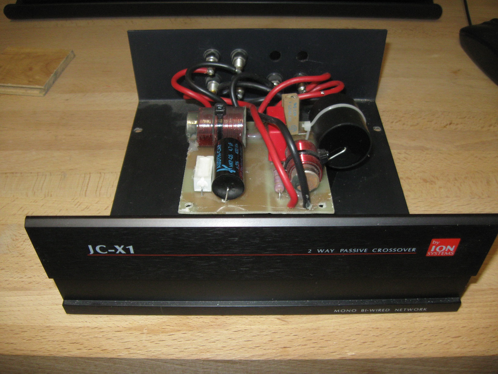
It would be nice if somebody can share the circuit diagram for the crossover from JC1a speakers. I really need it.
 
Last edited:
I've just opened up my passive crossover box (JC-X1) for you and drawn out the crossover network.
Otho9Ra.jpg

6UKFTWI.jpg


I can't measure the inductors, mH, accurately so have included their dimensions. If you ask Falcon they may be able to tell you the inductor value from the dimensions.

You probably downloaded the amp circuits diagramms when they were posted by lokh a few years ago. The active crossover values (JC1 new) for the tweeter is identical with all the other speakers, Kan, Isobarik so this is likely to be 3kHz. The woofer has different active crossover values than the other speaker.

The passive crossover had new capacitors added by a dutch guy I bought the speakers from. I assume they are the same value as the originals.

If you send me a PM with your email I can send you a few more pictures of the crossover, you can check if I have drwan the circuit correctly!

bUXPHTd.jpg
 
Last edited:
I've just opened up my passive crossover box (JC-X1) for you and drawn out the crossover network.
Otho9Ra.jpg
[/IMG]
(
Otho9Ra.jpg
)
6UKFTWI.jpg
[/IMG]
(
6UKFTWI.jpg
)

I can't measure the inductors, mH, accurately so have included their dimensions. If you ask Falcon they may be able to tell you the inductor value from the dimensions.

You probably downloaded the amp circuits diagramms when they were posted by lokh a few years ago. The active crossover values (JC1 new) for the tweeter is identical with all the other speakers, Kan, Isobarik so this is likely to be 3kHz. The woofer has different active crossover values than the other speaker.

The passive crossover had new capacitors added by a dutch guy I bought the speakers from. I assume they are the same value as the originals.

If you send me a PM with your email I can send you a few more pictures of the crossover, you can check if I have drwan the circuit correctly!

Are you sure that diagrams correct? It looks well dodgy to me! 4.7uF cap directly across the amplifier output? If it was after the choke that would be about right for a 2nd order filter... On the HF section the 0.47R resistor also looks dodgy to me...
 
Thank you Arkless for finding the mistake !
The image has been corrected and reloaded.
Regarding the 0.47R resistor on the HF section, the colour code is YELLOW VIOLET GOLD GOLD, it is probably a 2W MOX resistor, the other resistors are 5W wire wound.
I have tried to upload an image but as yet without sucess.

SUQVWu7.jpg

4.7R 5% :)
 
please note the resistor parallel to the HF inductor is 4.7ohms NOT 0.47 !
I have tried to upload a corrected image but without sucess.
 
I've just opened up my passive crossover box (JC-X1) for you and drawn out the crossover network.
Otho9Ra.jpg


I can't measure the inductors, mH, accurately so have included their dimensions. If you ask Falcon they may be able to tell you the inductor value from the dimensions.

You probably downloaded the amp circuits diagramms when they were posted by lokh a few years ago. The active crossover values (JC1 new) for the tweeter is identical with all the other speakers, Kan, Isobarik so this is likely to be 3kHz. The woofer has different active crossover values than the other speaker.

The passive crossover had new capacitors added by a dutch guy I bought the speakers from. I assume they are the same value as the originals.

If you send me a PM with your email I can send you a few more pictures of the crossover, you can check if I have drwan the circuit correctly!

Thank you very much! Will PM you mail email.


advertisement


Back
Top