
You are using an out of date browser. It may not display this or other websites correctly.
You should upgrade or use an alternative browser.
You should upgrade or use an alternative browser.
New PCB for shoebox size NAC preamp part IV
- Thread starter LoBo
- Start date
I do remember I got awefull confused when I stated mine and decided to build it up in stages from single rail to dual rail and got in a right mess.
Just stuff the board to bom 1.2 and you will have the bad boy dual rail symmetric supply which uses a Nert, this is the version that eveyone builds.
You get aproximatly +15v / -15v on the rails with respect to the Nert 0v point.
Just stuff the board to bom 1.2 and you will have the bad boy dual rail symmetric supply which uses a Nert, this is the version that eveyone builds.
You get aproximatly +15v / -15v on the rails with respect to the Nert 0v point.
The one thing that's not clear to me is whether or not the 0V from the Traco should be connected to anything. My understanding was that it's not connected (hence the need for only 2 chokes) and the NERT 'generates' the 0V rail - is this correct?
The Traco V0+ and V0- connect to the Nert.
The Traco V0 is not connected.
The nert V0 connects to power ground on the fish.
Only one Traco is used.
There is one common mode choke - two coils.
There are two differential mode chokes - single coils.

Thanks Tony - Symmetrical it is with 2 windings on the common mode choke.
Thanks all for clarifying!
It does get confusing.
Hope I got it right for you
")
I've completed the build of my 'fish to BOM 1.2 but without the Traco. I decided to test from a +/- 15v supply I have prior to adding the Traco. One channel is fine but the other is not. The filter stage is OK so the signal coming of the pot to the gain stage is OK but after that it becomes unstable. I'm seeing some hf oscillation at around 4MHz. My 1kHz test sine wave is in there too but there's no gain.
I've removed and replaced the 5 transistors in this section, the old ones all checked OK so no surprise when the problem persisted with the new ones. I've also reflowed the joints on the other components. I've checked the resistor values are correct but will re-check just in case.
In the meantime does anyone have any ideas how to debug? I have a 'scope, multimeter etc. to hand.
Now fixed - I had a 120R fitted at R134 instead of 12K. A little too much feedback! Damn my eyesight and those pesky colour bands, from now on everything gets measured before it get stuffed in...
Now for the Traco & NERT.
Another 'fish lives! Excercising far more self restraint than is usual I've resisted the urge to play music through the 'fish until the board was properly nestled in a nice modushop case with all the inputs and output etc wired up. Well last night it was finished and plugged in between my LP12/Linto and NAP140.
Bloody hell this thing's good! It was late so limited volume / time but even from cold with no burn in this is a major step up from my Avondaled 102 and that wasn't too shabby!
Need some decent knobbage for the front but other than that it's done. I can't wait to partner this with the HackerNAP once that's ready.
I guess most 'fishes that will be built have already been built but if you're contemplating building one just do it!
Another 'fish lives! Excercising far more self restraint than is usual I've resisted the urge to play music through the 'fish until the board was properly nestled in a nice modushop case with all the inputs and output etc wired up. Well last night it was finished and plugged in between my LP12/Linto and NAP140.
Blood hell this thing's good! It was late so limited volume / time but even from cold with no burn in this is a major step up from my Avondaled 102 and that wasn't too shabby!
Need some decent knobbage for the front but other than that it's done. I can't wait to partner this with the HackerNAP once that's ready.
I guess most 'fishes that will be built have already been built but if you're contemplating building one just do it!
It is very special is it not?
Expect the HackerNap to be in the same league, happy times are to come.
Still checking out my fish before connecting the real music sources - don't have a separate power amp yet so won't be able to really listen. All seems OK but No1 son's 'scope is picking up a fair bit of 1MHz noise, shed loads of it at ouput of Traco (expected) and about 5mV at +/- of NERT and similar at fish outputs - is this normal? Both channels same so unlikely to be a wiring fault. Only thing I can think off is common mode choke wound wrong - mine has both input wires at top and output wires at bottom. Should also say the mush level doesn't vary with volume setting much, you can see a bit more white noise but not much
I checked the output of mine and there is a fair amount of mush in the low MHz range. The level is of the order of a few mV pk to pk. I'd guess this was pretty standard, the filter does a good job of blocking much of the Traco noise but it looks like some higher harmonics still get through on to the supply rails. I'm guessing most (all?) power amps are bandwidth limited so some low level stuff at a few MHz isn't an issue.
Be nice to know for sure though.
Be nice to know for sure though.
sam_cat
C'est Crounchifique!
Rebuild into new case is coming along well:
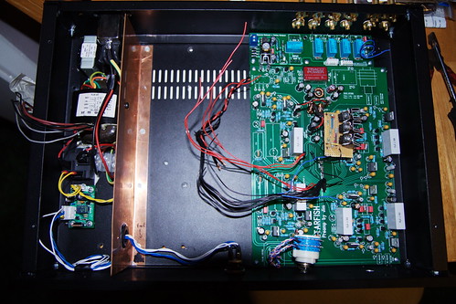
Starfish rebuild internals by Sam_catch, on Flickr
Just enough room to squeeze some goodies in there
Starfish rebuild internals by Sam_catch, on Flickr
Just enough room to squeeze some goodies in there
Sam, you need an earth bond on that copper screen in order that it may be an effective RFI / electrostatic shield. Sorry if I missed it from your picture but others may miss it also.
Of course it will prevent voltages from being capacitively coupled, but will do nothing to prevent magnetic flux leakage.
1/4" thickness of ferrous material will give about 20dB of attenuation.
Dont confuse the copper band on the out side of some transformers with your method of shielding. The copper band is continuous and caries and eddy current which in turn creates a flux in opposition to the main leakage flux thus offering some attenuation. A copper electrostatic shield some times placed between windings is not continuous, it always has a gap else it would cancel some of the main magnetising flux and reduce the transformers efficiency.
The core will often leak more at some points than others, usually at cable entry points so careful positioning and rotation can help. But I think this level of detail is normaly only required on instrumentation work.
However your R-core has about 1/10th flux leakage of a conventional E-I core so the R-core has effectively moved the its self three times further away than an EI-core. I think... (not doing the squared law very good this morning)
Edit, its the cube law not square law.