advertisement


NCC200 max voltage

glenn jarrett

pfm Member
whats the maximum voltage you can feed 2x NCC200 modules ?
the transformer i have is on the schematic of the amp i recycled it from as giving +/-53.5 v after regulation and smoothing but with nothing connected ( no load ) i get +/- 58.5 v across the caps is this because i have no load connected
and would this be ok feeding 2x modules ?
20210329_204447 by glenn jarrett, on Flickr
20210329_204640
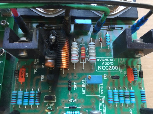
 by glenn jarrett, on Flickr
 
I suspect you're thinking of Voltage Regulation from the transformer, which is dependent on the current flow. In a "normal" situation, there is actually very little flow of current from the transformer, as it's usually just topping up the caps. Even a heavily pushed amp tends to draw very little current most of the time.

For example, when I have a 35V-0-35V transformer attached bridge rectifier and smoothing caps, the output voltage reads ±54VDC (or thereabouts), regardless of whether a load is attached.
 
would the modules attached pull it down enough to be safe ?
i dont want to connect the modules if the voltage is too high
i have read someone on here runs at +/- 55v
 
No!
ZTX653 is rated at 100V V(CEO), so +/-50V is the maximum supply voltage you should use.
 
Yeah, that's worth stressing. 58 volts is definitely too high. If your transformer is rated at 35V-0-35V, then you'll be fine.

I once tried a 40V-0-40V transformer, which would have resulted in approximately ±62VDC after smoothing. This is what happened:

NCC200_Kaboom.jpg
 
There was a thread here a few days ago about the use of a bucking transformer. Wondering if you could use one here to calm things down a little?
 
as I have high mains voltage in my house 250V my transformers have been changed to 33-0-33 as this gives just over 50vDC after smoothing

Mine are still 35-0-35V as they're too nice to remove. I have however installed a crossed digit network as part of the power up sequence.....

download-1.jpg
 
If you were using one transformer with dual secondaries, option 1 is what you'd do by default.

Since you aren't - I'd go with option two; simply becasue it halves the PIV and dissipation in the bridge rectifier. There's an extra diode drop involved on each rail, which is hardly significant; and I'd make the two windings meet at the 0v connection of the first two reservoir caps, not the point you've marked '0'' in the second diagram - so there isn't an ac charging current ripple across the resistance of the length of wire between it and the reservoir caps junction. That will make for an ac noise hum voltage. Such things can matter.

(that detail aside) I'm not sure the choice of basic approach amounts to a hill of beans, but that's likely what I would do.
 
Last edited:
I would go with option 1.
This provides the lowest resistance to charge the caps - only the slope resistance of one diode between the winding and the cap.
 
Id go for 2 but why not try both and see if you can detect any sonic difference/benefit between them, one of them you may prefer over the other.


advertisement


Back
Top