new naim boy
pfm Member
Over the past few months I have built a Naxo from bits lying around. I had to buy a few small caps, that's all. Probably cost about £5 for bits I didn't have.
The schematics were obtained from Neil Mcbride's site. The unit consists of four identical sections, two low pass and two high pass. In each of these sections there is a distinct low/high pass module, which I put on a detachable board to allow me to alter the crossover frequency. It all fits nicely on two matrix boards from Maplins, which I did intend to use for something else. Too many projects....
Each section has it's own regulator. Nothing fancy, there are loads of 317 based regs around costing very little and which do a great job.
I have an old pair of Alphason speakers with ribbon tweeters, which I have connected to the crossover set for the SBL 3.0khz crossover.
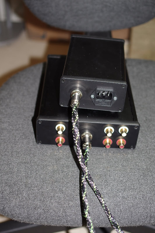
The whole thing was a bit of an experiment. But what an amazing revelation this unit is. If anyone is interested I'll post some pics. This unit is definitely staying in my system.
The schematics were obtained from Neil Mcbride's site. The unit consists of four identical sections, two low pass and two high pass. In each of these sections there is a distinct low/high pass module, which I put on a detachable board to allow me to alter the crossover frequency. It all fits nicely on two matrix boards from Maplins, which I did intend to use for something else. Too many projects....
Each section has it's own regulator. Nothing fancy, there are loads of 317 based regs around costing very little and which do a great job.
I have an old pair of Alphason speakers with ribbon tweeters, which I have connected to the crossover set for the SBL 3.0khz crossover.
The whole thing was a bit of an experiment. But what an amazing revelation this unit is. If anyone is interested I'll post some pics. This unit is definitely staying in my system.