advertisement


NAP180 Wiring Question

Suffolk Tony

Aim low, achieve your goals, avoid disappointment.
Hi folks,

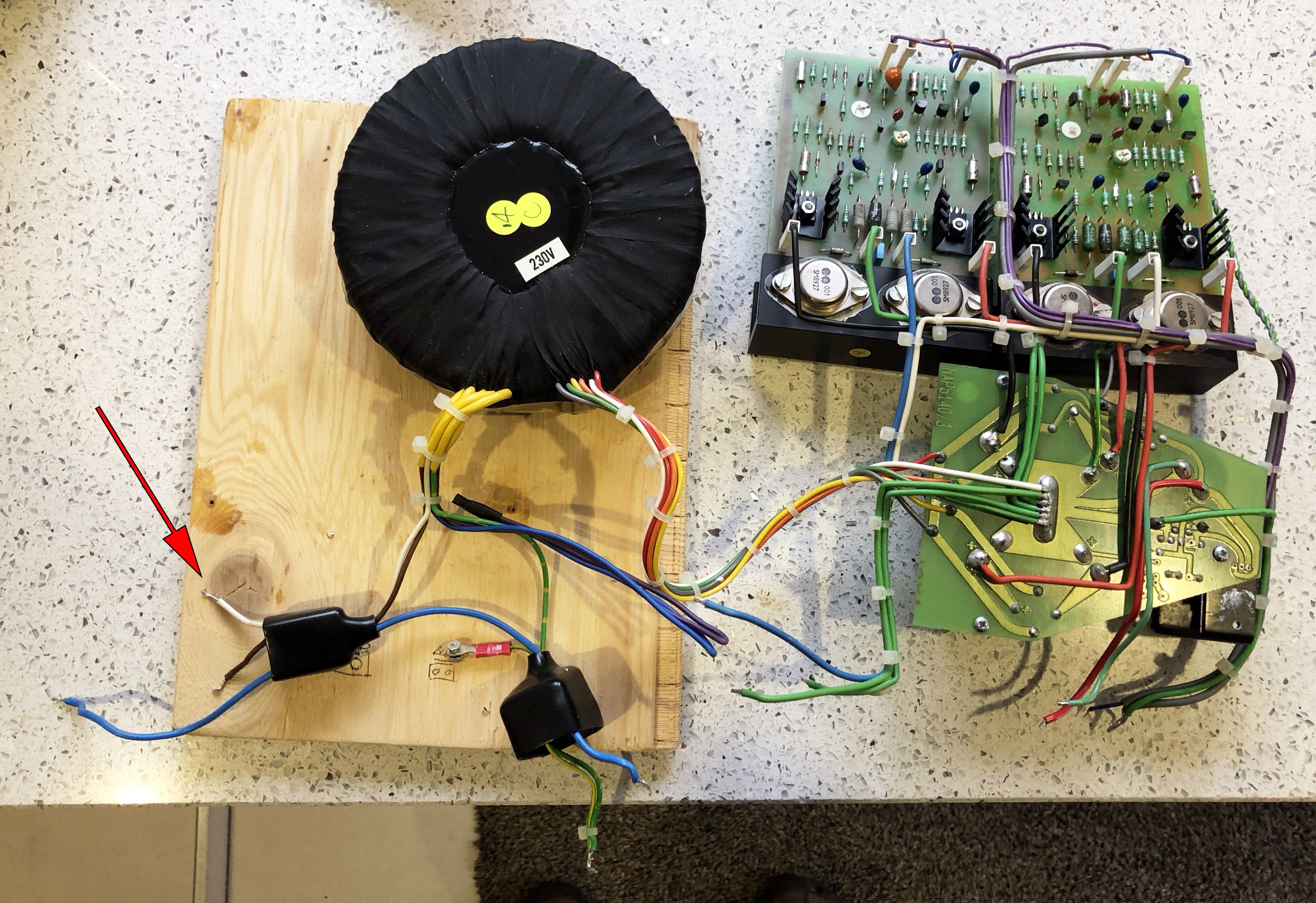
Just in the process of building up a NAP180. I've figured out most of the wiring, but there's one wire I'm a bit puzzled about - arrow marks it in the photo, the white one that goes to the transformer. It comes from the front switch, which I intend to do away with & just use a switched power input. Am I correct in assuming this wire can just be joined to the blue and brown wire in those circumstances?

lZls5AF.jpg
 
Hi Tony,
You appear to have the live wire from the iec socket to where the switch is missing. I think the white wire to the trafo is live and the brown is neg

but that is from memory, see if any one agrees or I will check later for you.
 
I think, will check later, that the brown is neutral and the white is live. That's based on the letter C on the transformer, the primaries are wired in different configurations for minimal radiated field.
 
Tony, IMHO the white is the counterpart of the blue wire on the switch. that is, you seem to miss the oveheat-sensor where the brown (live) wire connects first from the IEC socket, and from where the brown (live) part should go to the switch. (to note, I see no brown /live/ wire present from the IEC inlet at all). the blue (neutral) wire, however, goes directly to the other side of the switch with no interruption from the IEC socket, hence its present. then, from the switch, the brown (live) wire should go to the transformer's 'live' tap keeping the colour logic, and the white must be the (neutral) counterpart of the blue wire that also connects to another tap on the transformer. hope it helps
 
Thanks for your help folks. It's a bit odd - the blue wire must have gone to the switch. But why would you have three wires to the switch? Something's missing and/or in the wrong place. Maybe a missing brown wire from IEC socket to switch, then both live & neutral are switched?
 
The missing wire is the live and it goes to and from the thermal trip. Yes Tony its a double pole switch that is wired to switch the live and neutral.
 
From IEC socket, a blue wire straight to one pole of the switch and a yellow wire from Live to the other pole of switch via the thermal cutout. On the switch the poles join the transformer brown to the neutral (Blue) and the the white to the live (Yellow). Taken from my wiring instructions in production.
 
So is the thermal cutout in the switch assembly? And can I just, from a switched IEC socket, just basically connect white to live & brown to neutral?
 
No, it’s bolted to the chassis underneath the amplifier boards and close to the heat sinks. You can see the two yellow wires going to it in the photo linked to in post #9.
 
Thanks Misterc6, that explains it. But I don't have the thermal cutout, only what you see in the photo.
 
In a complete Naim NAP180 the entire case helps by acting as a heat sink. It is rare for the thermal cutout to be triggered in normal operation but it is a safety feature which breaks the live connection when things get too hot. The choice is yours, you can either use one or not. If the parts you have came from Les W at Avondale you should ring him and I’m sure that he’ll have a spare one. Alternatively, post a wanted ad in the DIY Classifieds here on PFM.
 
… I don't have the thermal cutout, only what you see in the photo.
NC (Normally Closed) thermal switches with good enough contact current rating are readily available, e.g. from CPC here if you can't find one elsewhere. See the article here for some further information.

If you have to buy one a key question is the right cut-out temperature. I don't know the proper temperature for this application. But at 60 degrees Celsius the heatsink would be too hot to touch and the article says no more than 80 degrees Celsius. I am sure someone can advise properly.
 
One more thing to be aware of is the arrangements of the signal grounds. They're fudged for a 4 pin socket and there's a pair of violet wires that are capacitively coupled to the green wires in the wiring loom to keep noise to a minimum for these transformers and layout. Any change from the old layout or input socket wiring may render the noise level of the amp excessive (or not). You can check this with the inputs shorted and an AC voltmeter or scope on the outputs. You should see a sawtooth waveform due to the level of PSRR of these amps.
 
Thanks Misterc6, that explains it. But I don't have the thermal cutout, only what you see in the photo.

I have a spare and proper one from my NAP160 and am willing to send it to you FOC - but it should be shipped from Hungary, the cost of which is £10. let me know how to proceed, please
 
Many thanks for your kind offer coltrane. I'll probably contact Les at Avondale tomorrow, where the 180 bits came from, see if he's got one.
 
Here's a sum question on that internal layout of boards in the NAP180. Why are the main boards at the front of the amp with long of cabling from all the inputs and outputs on the back panel?
Seems counter intuitive.
 
the PSU caps (and, in some NAPs the rectifiers, as well) are located at the back of the main PCBs, thus, my take is that Naim wanted to avoid interference getting in the input stages from there. that's perhaps why even the connecting signal wires between the DIN/XLR inlet and PCBs are shielded


advertisement


Back
Top