advertisement


Naim Nap140 original parts service list

E38-BBE60-151-B-4119-9825-283750-BECC39.jpg

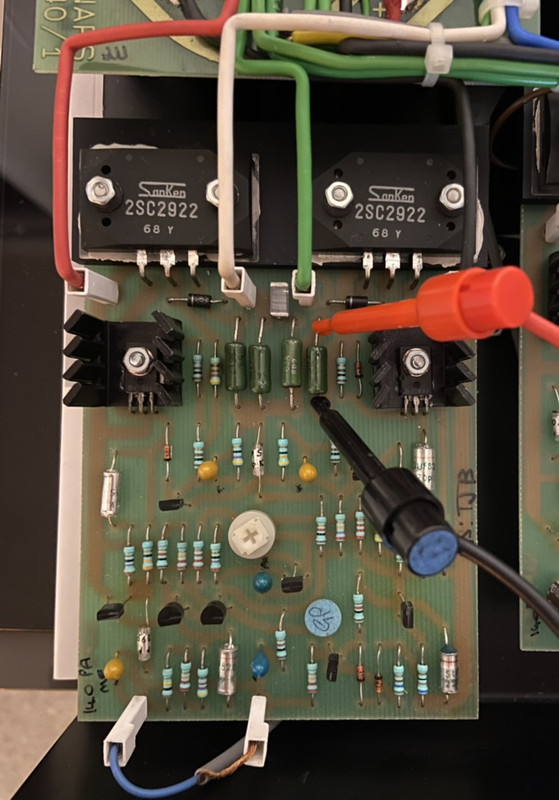
This is how I’m measuring for the bias of the amp in mA’s. It’s currently at 4.2mA when the amp has been on for 30mins with nothing connected but I’m not sure what it officially should be.

I don’t want to change the sound really as I’m very happy with how the amp sounds so I will keep caps to the original spec. Would it be worth changing the small silver caps on the board too? And if so does anyone know what they are?

Thanks for any advice or input on this guys. It’s all a bit of a learning curve for me but without asking I will never learn.

Those silver chaps are polysytyrene (or polysummink) & iirc don't tend to get changed regularly in a service like the ones you've done. They're like films & tend not to degrade.

Btw you're measuring 4mV on your DMM, which equates to 24mA using the C=I/R equation (I think I've got my equation letters in the right order).

I measured my bias across the last green 0.22 resistor, the other end one in the row to yours, but it's probably same-same.

Capt
 
Yes, no need to recap the styrenes, also make sure not to let them get too hot when you solder near them, they dont like heat...
 
Yes the readings on both resistors are more or less the same @ 4mA
I have one channel done so going to start the other tonight and hopefully have some music playing tomorrow afternoon

My worry is something going wrong and ending up getting DC at the speakers but I will leave it running for a few hours before connecting up to anything of value.
 
Those silver chaps are polysytyrene (or polysummink) & iirc don't tend to get changed regularly in a service like the ones you've done. They're like films & tend not to degrade.

Btw you're measuring 4mV on your DMM, which equates to 24mA using the C=I/R equation (I think I've got my equation letters in the right order).

I measured my bias across the last green 0.22 resistor, the other end one in the row to yours, but it's probably same-same.

Capt
V=IR, so I=V/R. If you measure 4mV, which is 0.004v and 0.22R the current is 0.004/0.22 or 0.018A.

Thing to do is set it to that, put the cover on and leave it for a couple of hours to reach thermal equilibrium, then measure and set again. The recommendations I've seen (and used) are for more like 4.5mV per side, (but not for a NAP140 with the Sanken outputs, so who knows). The process also recommended a 4R resistive load on each output during warm up. This will cause the offset voltage to generate a little heat and will be realistic for the amp in use. Also I'd measure across both resistors, for no other reason than the more volts the more accurate the meter might be.
 
Think I have made an Error with my calculations and getting confused.

When measuring between the far left resistor or the far right resistor I`m getting 4mV.
 
V=IR, so I=V/R. If you measure 4mV, which is 0.004v and 0.22R the current is 0.004/0.22 or 0.018A.

Thing to do is set it to that, put the cover on and leave it for a couple of hours to reach thermal equilibrium, then measure and set again. The recommendations I've seen (and used) are for more like 4.5mV per side, (but not for a NAP140 with the Sanken outputs, so who knows). The process also recommended a 4R resistive load on each output during warm up. This will cause the offset voltage to generate a little heat and will be realistic for the amp in use. Also I'd measure across both resistors, for no other reason than the more volts the more accurate the meter might be.
Good day
I testing from 2.8mv to 4.8mv
And sound is little different
I think better solution is 4 or 4.6 mv (current in output stage is not be up over 20mA)
Try set 4mv and check this one after one hour working after that trim output current to 4.6mv.

If you watch to NAP300
output currents is more high but i think this is not good for Naim quasy schematics and sound because class B working with low currents :))
 
Last edited:
Think I have made an Error with my calculations and getting confused.

When measuring between the far left resistor or the far right resistor I`m getting 4mV.

How are you getting on- has the confusion gone?

Paul R corrected my bad "c=i/r" guess, as to the simple equation relevant to your bias test. It's V=IR..

[ V=IR, so I=V/R. If you measure 4mV, which is 0.004v and 0.22R the current is 0.004/0.22 or 0.018A (= 18mA) ]

So you measured in millivolts, across the 0.22r resistor (either your one or mine it doesn't seem to really matter).
And you read 4mV: so using the I=V/R equation, the bias is 18mA. (If you read 4.5mV, then the bias is.. 20mA ? Something like 20).

Mine's set to 4.5mV as I like the way the amp sounds like this: I think yours maybe has Sanken transistors too?
 
The output transistor type should not change the bias point; for pretty much any quasi-comp circuit you want about the same point, and IT IS NOT CRTICAL - you are playing a game of tradeoffs!

For a large signal, +ve or -ve, the load is handled by one transistor via one emitter resistor. The "effective output impedance" of a transistor (including combinations like Darlington or Szilkai) is given by 26/I, where I is the current in mA. For a decent output current say 1A, this is tiny compared with the emitter resistor, so the effective output impedance is just that of the resistor, 0.22R.

Round zero volts, we have two transistors, and two resistors, sharing the load. If we have say 26mA of bias current, each transistor has an impedance of about 1Ohms, so we end up with an impedance of about 0.6R (1 + 0.22) /2. At 52mA output current, one transistor is just on the edge of turning off, while the other takes all the current, so has an impedance of 0.5 Ohms, giving an output impedance of 0.7, not too different to the 0V value. As we go up from this the impedance will slowly fall to the large signal value. None of this argument depends on the transistor types.

In fact, you can see that you can get a small advantage by running a bit more bias, as the small signal value will sit closer to the large signal value.

Of course, in reality these effects are massively diluted by the negative feedback, but I wanted to explain it is not worth sweating about decimal places!!
 
In fact, you can see that you can get a small advantage by running a bit more bias, as the small signal value will sit closer to the large signal value.

Good day
Not good for Naim sound stage
output current over 20mA :))
But you have anytime chance to listen :))

More output current more warm in output transistors after that you have a termal circle with output stage and “current sensor” transistor if him h21e is not enough your output stage is heat over 70 plus degrees termal fuse is open and your NAP140 is off :))

So if you connected “current sensor” transistor at amp aluminium case
you have chance to large output current up to 100ma (class AB) or up to 300-500mA (class A) but sound is not good and not Naim :))
 
Last edited:
What do naim suggest as bias current within their service? I thought it was around 30mA. I think that equates to around 8mV iirc.
 
20mA. 8.9mV over 0.44R. Just get it somewhere in the 8-10mV zone and reset it after the amp has reached thermal equilibrium.
 
There are two of them in series. Measuring across both is simplest. And the more volts the better the meter works.
 
I think I set it around 40mA across the two outside resistor’s after getting upto temperature.
It’s up and running with no issues. I will measure it again to double check and report back probably next week as works manic at the moment.


advertisement


Back
Top