advertisement


Naim Nap 135 Servicing thread

If you really must squeeze two 47uF tants into one pair of holes the best way to go about it is to scrape down the legs of the tants with a craft knife until they'll go in rather than try to enlarge the hole.

An alternative and perfectly satisfactory approach is just to solder one in and leave the legs a bit long and then solder the other across the legs on the "dark side" of the board.

I built my 160 clone that way.
 
Some modern tantalums (AVX for sure, maybe others) don't have particularly thick legs anyway, and the Naim holes are a bit bigger than they need to be. I've found in the past that two 47uF tants can fit into a single pair of Naim holes with no faff involved. Pre-bend the legs so that they sprout out of the circuit board and neatly branch out to each tant, don't stuff the tants down and tight together in the hope of keeping the legs as short as possible, that might put some stress on the legs/joints.
 
I took alot of pics with my crappy camera, appologies as this was the best.

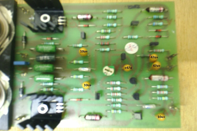
Its a NAPA6-4 Board I purchased from this parish a few months back.
I have marked the Tants as I can see them with a magnifying glass

uY5sUbU.jpg


Im guessing that these are original STC mentioned by Colasblue as they dont look like the nice new AVX ones I have to go in.
Also mentioned in this thread are caps mounted incorrectly
Can anyone confirm I have the correct polaritys marked
 
That's actually a fairly late board revision to have those two 47uF caps in parallel and in their own holes.

It may just about be new enough to have had yellow Kemets fitted as original equipment, they certainly aren't STC.

OTOH somebody may have already changed them.

The polarities you have indicated are all correct.
 
They could possibly be AVX, the body and text the same colour, both say 106 and 35+ for the 10uF
My new ones have that inverted L over the text as the installed ones dont.
Good News that the polarity are correct, I guess it only adds to this thread in a positive way! :)
Time to get the olde Weller warmed up!
Thank you for your help and confirmation.
(Im looking forward to New Years Eve to really try these out! 500VA, HackerCap and a 12" Bass driver each)
 
In my haste when servicing my 135s according to this thread a year ago, I forgot to change the 100uf feedback tants- just got around to doing it this week. My golly what's difference! System really boogies now!!

I used 100uf AVX Tants as I didn't want to drill the holes out for 2 parallel 47uf caps. I figured if the 100uFs fail in 5 years, I can buy two new ones at one pound a piece!

Regards
Matt
Hello guys,
not trying to hijack the post (moderators may move and open a New thread..) however quoting Matt reply due to am finding 100uF 16v tant in my 135s at feedback position..
unofficial service made more than 5 years ago.. and hearing a crackling and hum in both my speakers.. am thinking to go for double 47uF MMK each to ser how they behave and if cure to crackling is round..
Any hint by the experts will be welcome..

Very good Colasblue by the way, Thanks a lot for sharing,
Matt.
 
Crackling is never the feedback cap, it's always the 10uF/63v axials on the power supply board.
 
Cap swap done,
just turned on the thing and scratching disappeared! (thanks a lot Mark. 50Hz hum remains in the speakers but this is for another story, not really a hum.. it sounds like a tictic @ 50Hz frequency).
Hopefully will be able to make some serious listening soon.

Oddly enough the scratching from the other channel/135 in the speakers disappeared too.
Will of course substitute 10uF Pana NHG electrolytic caps on regulator boards of the other 135 as well, soon.
I had some 47uf Elna Silmic II to try too and changed these as well.. would like to post the picture.. soon..

Trimmers of this channel1 135 being oversensitive and not easy to set.. but eventually set Naps voltage @ +40.0V -40.6V, Napa bias @ 7.0mV.

Having a very smooth pop from the speakers when turning on this channel1 135.

Not having a pro multimeter indeed.. but measured DC Offset of 6.0mV (DC) and 1.2mV (AC).

I am wondering if the 50Hz hum I am hearing in the speakers is now due to the measured 1.2mV AC voltage. Could it be due to this "small" AC voltage?
 
Some one said you can get a hum if the wires to the thermal trip aren’t flat to the bottom of the case.

Pete
 
Thank you for asking me to double-check, Pete.
Assuming you mean the 2 long yellow wires, checked back and they are running flat to the bottom in both amps.

The channel2 135 underwent the same above treatment now, with the scratching already solved from channel1 (!!!).
Measured a DC Offset of 15.2mV (DC) and 2.2mV (AC).

I plugged the hifi ac power distributor onto a different plug in the wall (now 10A only..) and most of hum in the speakers is gone (!!!).
Still some other noise to be improved (a 50Hz tictic) but will leave it for another story (very likely coming from the modded pre 32-5+Snaps), and dreaming of a dedicated mains line..
 
The current naim spec for the 47uF and 100uF tants seems to be 6V but anything over is fine.

My BoM excludes the 10uF SoA tants since I removed the circuit and also the 100uF tant since I replaced it with the Rifa MMK's I've also used a lot of radial caps where there would have originally been axials

The BoM for a full factory service would be

15000uF 63V SiC Safco Felsic capacitors x 4
10uF 35V Kemet tantalum x 10 (6 for amp boards and 4 for fan boards)
47uF 6V Kemet tantalum x 6 (one for each VBE cap and two to replace each original 100uF feedback cap)
10uF 63V Vishay BC axial electrolytic cap x 4
47uF 40V Sic Safco Promisic axial electrolytic cap x 4 for regs boards
47uF 40V axial capicitor x 2 (fan boards)
470uF 63V Axial Capacitor x 2 (fan boards)
4 x 3K3 1W resistor
4 x 10V zener diode

Even if sticking to factory spec fairly closely it would e sensible to substitute the 10uF 63V BC Vishay cap with something else since it's the least reliable component in the amp and also up rate the 3K3 resistors

(added 28.6.19)


advertisement


Back
Top