
You are using an out of date browser. It may not display this or other websites correctly.
You should upgrade or use an alternative browser.
You should upgrade or use an alternative browser.
NAC 72 (loss of signal on left channel).
- Thread starter Luca
- Start date
Alan Chung
Member
Have you tried swapping the 321 cards between the two channels in the 72 and see if the problem follows the card swap?
Mynamemynaim
38yrs a Naim owner
Have you tried swapping the 321 cards between the two channels in the 72 and see if the problem follows the card swap?
In his original post he said he'd tried that
Luca
pfm Member
I recleaned all in a more vigorous way yesterday. I remembered that with the blue Alps in my Eposure VII, the only way to sweep away completely the oxidation (without chemical products) is to turn quickly the potentiometer hitting on both the run ends. I've tried this method also on the Alps of my NAC72. After this treatment it seems smoother than before. Tinkering all the switches I noticed a strange fact. When I change input only one switch causes a bumping noise in the speakers. In other words, if I change from aux to phono or reverse I hear a bump in the speakers. The same happens when I switch the mon/mute device with the imput selector put on phono and not if it is on the other settings. I haven't another 72 for comparison so ask you if it is normal.
As I wrote before, there aren't phono or tape boards in my pre and all them are replaced by linking wires.
Just Now, I’m listening and the defect is gone but this happened, for few days, after the previous cleanings.
As I wrote before, there aren't phono or tape boards in my pre and all them are replaced by linking wires.
Just Now, I’m listening and the defect is gone but this happened, for few days, after the previous cleanings.
Mynamemynaim
38yrs a Naim owner
If it does turn out to be the volume pot
And you don't want to go the (highly recommended by me!) RSL cards direction
Have you considered a stepped attenuator with quality resistors in it ....this should offer a nice audible improvement and sort the problem
And you don't want to go the (highly recommended by me!) RSL cards direction
Have you considered a stepped attenuator with quality resistors in it ....this should offer a nice audible improvement and sort the problem
Luca
pfm Member
@ Mynamemynaim, my plan is to build a new preamplifier with new boards powered by ALWSRs (all inside the same enclosure) next winter (in my country the iper-hot summer isn't the best season for DIY audio works). It will have a stepped attenuator with quality resistors. My effort for now is to fix the problem keeping the original parts.
I have found some issues and I'm doing checkings.
Are the ALWSRs inside your NAC 72 connected in remote or local sense?
I have found some issues and I'm doing checkings.
Are the ALWSRs inside your NAC 72 connected in remote or local sense?
Mynamemynaim
38yrs a Naim owner
Ahh a stop gap repair until your dream preamp is built....I understand now.
TBH I didn't really understand the benefits of local sense mod ...so left them all (I use 6, two in the hicap clone and 4 in the 72) in remote mode
TBH I didn't really understand the benefits of local sense mod ...so left them all (I use 6, two in the hicap clone and 4 in the 72) in remote mode
Luca
pfm Member
Ahh a stop gap repair until your dream preamp is built....I understand now.
TBH I didn't really understand the benefits of local sense mod ...so left them all (I use 6, two in the hicap clone and 4 in the 72) in remote mode
About the ALWSR boards, I'm not sure when is better to connect in local or remote scheme. I did not find this info on PFM. Please can you explain to me? I've a work in progress. It is a pre phono MM with 2 NA322 supplied by ALWSRs inside the same case. I'm afraid I have chosen the wrong connection mode.
I believe you will want local sense.
Luca
pfm Member
I believe you will want local sense.
Thank you for the answer. Years ago, I wired my ALWSRs after reading here: https://pinkfishmedia.net/forum/threads/hi-cap-2-schematic.46148/page-3#post-579042
This was the only info I found.
For a while I feared it wasn't right because I believe that the noise I hear in the speakers, when I switch on the phono input, is due to a bad/wrong ground connection in the pre phono I'm putting together. I will post images ASAP.
Mynamemynaim
38yrs a Naim owner
There is a full ALWSR manual available on line...just Google it and you should find
I printed off the manual when I built my first set (some years ago) and keep it to hand when repairing or modding
But as mentioned...I failed to understand when to use local or remote...so went for the remote
I printed off the manual when I built my first set (some years ago) and keep it to hand when repairing or modding
But as mentioned...I failed to understand when to use local or remote...so went for the remote
a.palfreyman
pfm Member
IIRC you only need remote sense for loads which vary in their current consumption as the remote sense will correct for the impedance in the supply wires as the output impedance of the ALWSR is so low. This can cause stability issues though, so probably better to use local sense, particularly if the load is relatively constant.
Luca
pfm Member
IIRC you only need remote sense for loads which vary in their current consumption as the remote sense will correct for the impedance in the supply wires as the output impedance of the ALWSR is so low. This can cause stability issues though, so probably better to use local sense, particularly if the load is relatively constant.
Thanks, this is exactly what I wanted to know.
I'll post the pics today in the evening.
Mynamemynaim
38yrs a Naim owner
Thanks @a.palfreyman that's cleared that up
I have zero instability and great sound (luckily?) so will stick with what I know for now...")
I have zero instability and great sound (luckily?) so will stick with what I know for now...
Luca
pfm Member
I'm glad to introduce to you my ECO pre phono MM . I called it ECO because the case is made of recycled pieces of alluminum, left after other buildings, so it is ECOnomic and ECOlogical . It is a work in progress so many things are provisional.
In the first photo you can see the rear panel with two DIN sockets. The white one is the input from the PSU while the black one is the PSU output to other phono boards.
 20220210_115224[11] by Luca B, on Flickr
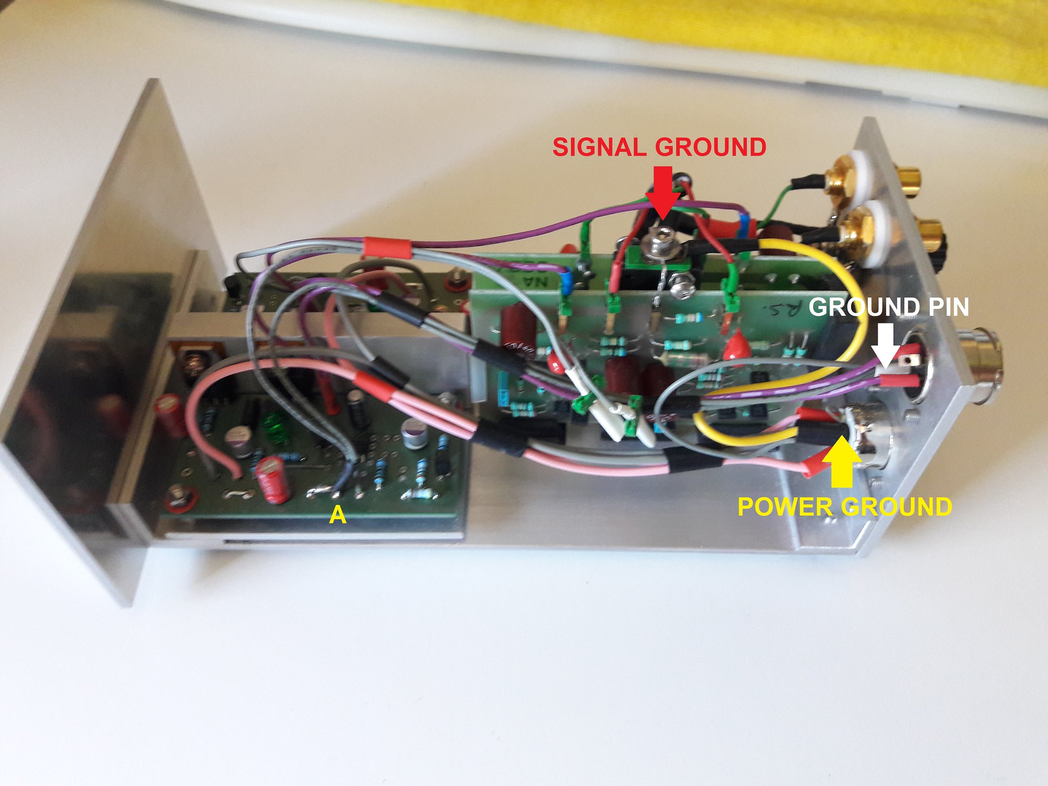
I have a doubt about the connection of the GND (point A in the photos below) of the ALWSR. I think it is correct to link it with the GND of the NA322 and the GND pin of the output socket? I'm wrong?
 20220705_115541 by Luca B, on Flickr
The signal connections:
 20220705_120045 by Luca B, on Flickr
A top view:
 20220705_115801 by Luca B, on Flickr
. I called it ECO because the case is made of recycled pieces of alluminum, left after other buildings, so it is ECOnomic and ECOlogical . It is a work in progress so many things are provisional.In the first photo you can see the rear panel with two DIN sockets. The white one is the input from the PSU while the black one is the PSU output to other phono boards.
20220210_115224[11] by Luca B, on FlickrI have a doubt about the connection of the GND (point A in the photos below) of the ALWSR. I think it is correct to link it with the GND of the NA322 and the GND pin of the output socket? I'm wrong?
20220705_115541 by Luca B, on FlickrThe signal connections:
20220705_120045 by Luca B, on FlickrA top view:
20220705_115801 by Luca B, on Flickr
Last edited:
chiily
PFM Special Builder
I can't quite see in the pictures, but don't take the signal gnds to your star gnd and then back to the signal gnd input on the MM cards. I did that with a pair of 323 cards and was very disappointed with the results, loss of sparked and clarity to the sound.
Best way is to connect the signal and the incoming signal gnd directly to the signal and gnd inputs on the MM cards. And as a separate connection from the card's PSU gnd to the star gnd.
I'll try to find the thread from many moons ago were I had the gnds incorrectly wired.
There you go, second post from @Jiiim
https://pinkfishmedia.net/forum/threads/some-more-phono-card-fiddlings.45649/
Luca
pfm Member
I can't quite see in the pictures, but don't take the signal gnds to your star gnd and then back to the signal gnd input on the MM cards. I did that with a pair of 323 cards and was very disappointed with the results, loss of sparked and clarity to the sound.
Best way is to connect the signal and the incoming signal gnd directly to the signal and gnd inputs on the MM cards. And as a separate connection from the card's PSU gnd to the star gnd.
I'll try to find the thread from many moons ago were I had the gnds incorrectly wired.
There you go, second post from @Jiiim
https://pinkfishmedia.net/forum/threads/some-more-phono-card-fiddlings.45649/
Thanks for the tip. I put a provisional staple, made of two wires twisted together between the signal ground star and the card's gnd. A temporary connection made waiting to understand if it is better to link the card's earth also with the GND of the regulator. Did you do this last connection? In other words, do you linked only the incoming signal earth with the gnd inputs on the MM cards?
Luca
pfm Member
 ALWSR connections
chiily
PFM Special Builder
I didn't use a signal gnd star. R and L cables, signal and gnd direct to the card's signal and signal gnd. Power to the power connector and power gnd to power gnd star and then from there to the powers gnd on the card.Thanks for the tip. I put a provisional staple, made of two wires twisted together between the signal ground star and the card's gnd. A temporary connection made waiting to understand if it is better to link the card's earth also with the GND of the regulator. Did you do this last connection? In other words, do you linked only the incoming signal earth with the gnd inputs on the MM cards?
Does that make sense?
Luca
pfm Member
I didn't use a signal gnd star. R and L cables, signal and gnd direct to the card's signal and signal gnd. Power to the power connector and power gnd to power gnd star and then from there to the powers gnd on the card.
Does that make sense?
It makes sense! I also connected the power gnd on the cards and the power gnd star by the yellow wire.
Your description is an answer to my other question. There is no need for connections between gnd on the regulator and gnd on the phono cards. Thank you again. I'm going to finish the wiring in a better way: removing the staple in the signal GND star; putting signal wires from the phono RCA earth directly to the ground on the phono boards; removing all the wires connected to the point A. I'll let you know if it works better.