
You are using an out of date browser. It may not display this or other websites correctly.
You should upgrade or use an alternative browser.
You should upgrade or use an alternative browser.
Leak TL/12 Plus / Point One Plus
Old Valve Git
pfm Member
Keep going Tony! It will be worth it.
Tony L
Administrator
I'm a bag of nerves watching the thread, it's captivating and nerve racking at the same time.
I’m pleased I pulled the boards out, it’s enabled me to get a lot of dirt and grime out, plus very closely inspect the soldering etc. FWIW I can see nothing wrong with either the board wiring or the chassis looms. It will also make it easier to swap out the 3M3 resistors, it’s just easier to see what I’m doing. I’ll do a couple of other things too while I’m at it, e.g. I do have a fresh new matching pair of the little polystyrene caps (C7), so I’ll stick them in, and I think I have spares of R1 so I’ll do those fresh as I never liked the way I did them (I’ll properly neat-freak it this time!). I don’t think it is the problem, but I ended up bending the resistor legs way closer to the body of the resistor than I like to do. With the board out I’m sure I can get it way neater using the forceps to get really neat clean bends away from the actual resistor body. Everything I can absolutely rule out is something else the issue can’t be. This done the boards will only have new components. Everything old is gone.
@Tony L
You sure have persistence chief, in fact, I’m sure I remember you talking about stir-frying the bearings for your TD124 motor for optimum performance?
That was three or four iterations ago! I later found a far better way of loading sintered bronze by dropping the bushings into a capped syringe full of oil and using the plunger to create a vacuum. It gets the oil right into where it needs to go without needing heat. I’ve since replaced the bushings with brand new ones, in fact every bronze bushing in the whole deck has now been replaced. It is running very well indeed these days and seems to be getting better as it runs in (it is effectively a new one now!).
toprepairman
pfm Member
Morning Tony.
When you took all the voltage readings previously, was that when the amp was humming or not?
When you took all the voltage readings previously, was that when the amp was humming or not?
simonpyeman
pfm Member
I hope it doesn’t turn out to be the OPT.
Curiously, I had a faint crackle on one of the PYEs that came and went a bit: sometimes it would all but disappear when fully warmed up, other times that didn’t seem to make a difference. I spent several years changing valves, renewing resistors and caps etc. The OPT primaries measured ok consistently so I just couldn’t figure it out. Eventually the crackling became more constant and louder and then, finally the measured primary resistances became unbalanced as one side increased. After disconnecting the transformer, one primary became open circuit. After sitting around for a couple of months, the other side went open circuit too! I sent it to Ed Dinning in the North East who diagnosed “green spotting”, a corrosion normally caused by damp: Cornwall does damp really well.... (He reverse engineered the windings as no spec could be found and now it’s totally quiet and running beautifully.)
Good luck with the fault finding: it’s really interesting reading, and I have one of those amps next on the mending pile!
toprepairman
pfm Member
That's what I was thinking.
Tony L
Administrator
When you took all the voltage readings previously, was that when the amp was humming or not?
No idea. It was driving an 8 Ohm dummy load with no input connected. I’m not really prepared to probe about with a £2.5k pair of LS3/5As attached (I have no scrap speakers)!
Progress is good. I’ve fitted the metal film 3M3s and reflowed/cleaned-up every single joint on the two boards, I’ve just washed them again and will post pictures later. I’d put money on them being spot on. They are looking very good.
PS As I say money is zero issue, there really is no upper budget for this. If it takes either having all the transformers re-wound or stealing the 8778s from the grey Stereo 20 (assuming the end caps are interchangeable) are then that is exactly what I’ll do. I just want to know what the issue is! Once diagnosed it can be fixed.
Tony L
Administrator
Here’s the current state of play with the boards:
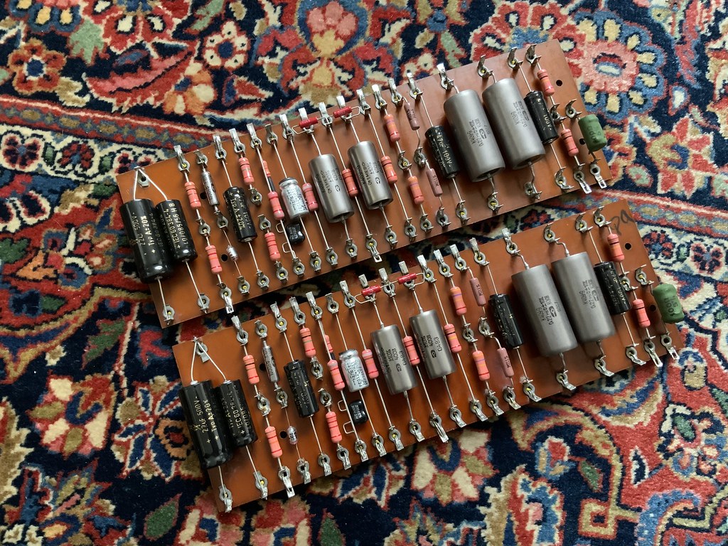
Top: New 3m3 resistors, new polystyrene caps, every single joint reflowed. The writing on the F&T caps didn’t really like being sprayed with isopropyl alcohol so has gone missing in places. Annoying, but more important to really clean the board IMHO.
Bottom: Rather cleaner than before!
I really can’t see anything wrong here, though if anyone else can please shout out now! It is so much easier working on these things outside of the amp!
John_73
pfm Member
...who diagnosed “green spotting”, a corrosion normally caused by damp: Cornwall does damp really well.... (He reverse engineered the windings as no spec could be found and now it’s totally quiet and running beautifully.)
With the cowls off, my stereo 20 had a few green marks on the transformer wires just visible before the soldered tag connections. Cleaned them off as best I could, and thankfully the wire underneath seemed fine. It also spent all it's life (until 2019) in Cornwall!
Tony L
Administrator
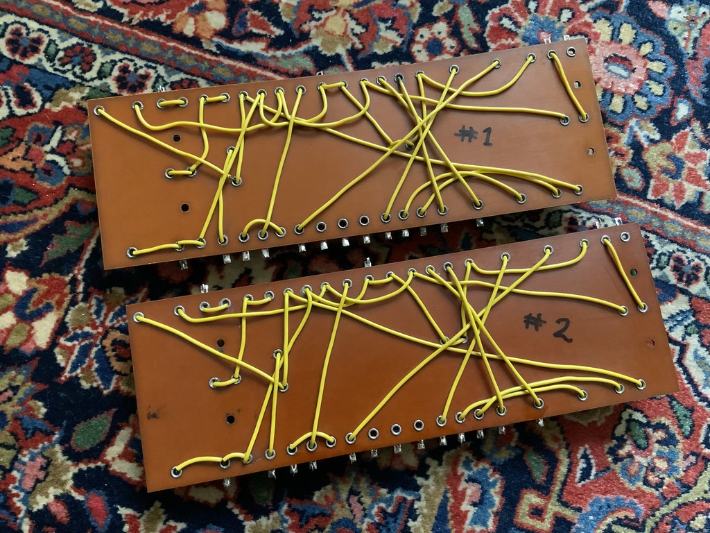
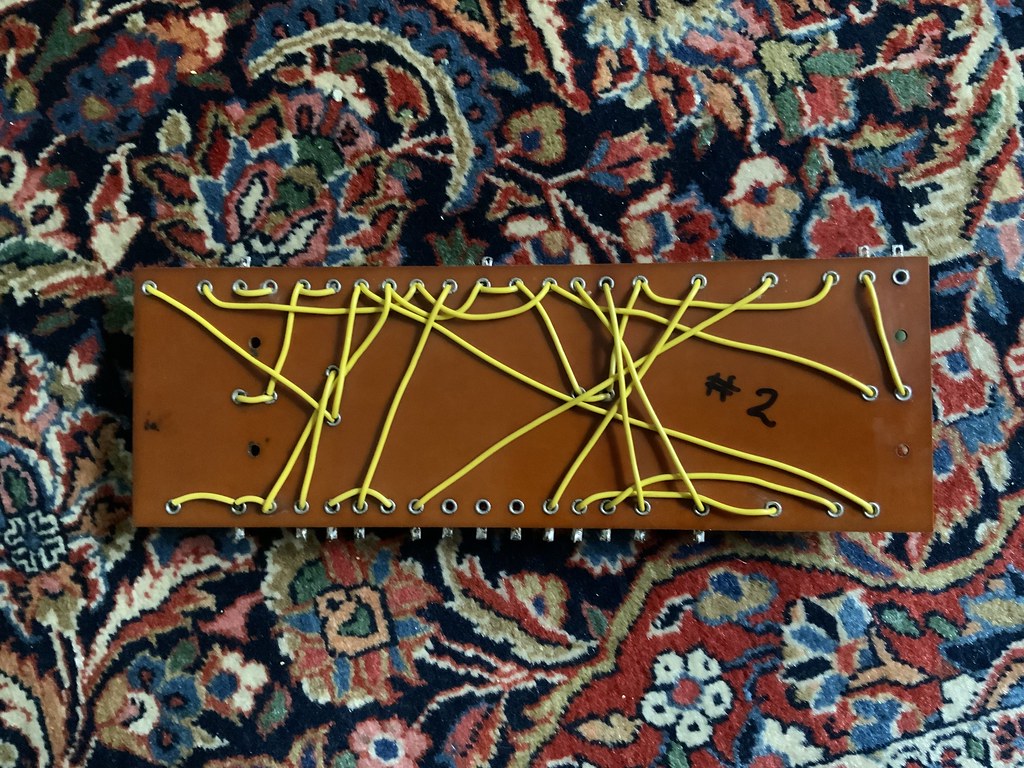
Here’s amp #2’s loom. I’ve neat-freaked R1 on both amps as I had spares and didn’t like my original bending. It is so much easier working without the board in the way! I’ve cleaned the looms as well as I can, and I can’t see any issues.
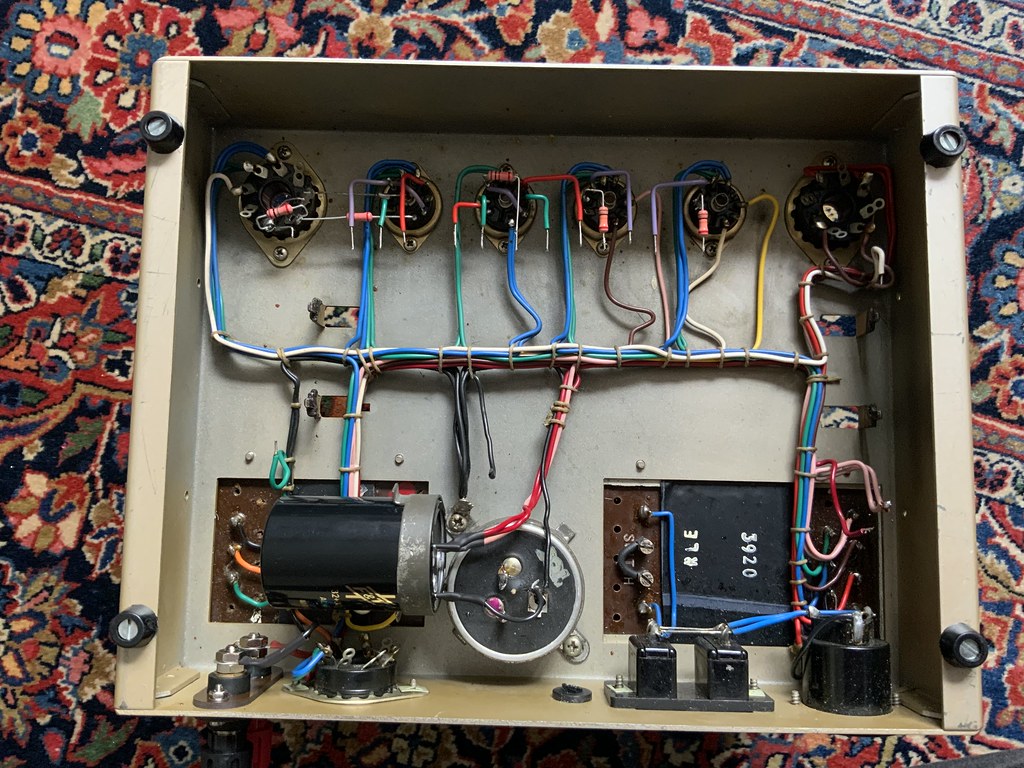
Looks fine. I'd be tempted to take all the transformer cowls off Mr Buzzy next and see if there's any obvious signs of corrosion or perhaps a dry joint on any connections.
I took the outer one off way back in the thread when tracing a rattle (loose star washer). It looked fine to me. I cleaned up all the connectors etc, but nothing looked bad.
I suspect it makes sense to only do one test at a time. I’ll swap the boards between the amps. If the problem still persists which chassis it is present on will tell us a heck of a lot.
As I see it there are three logical possibilities:
a) Problem is gone: it was the carbon 3m3s or a bad joint somewhere.
b) Problem moves with the boards: it is a component or wiring issue.
c) Problem stays with the chassis: it is an output transformer or loom issue.
Obviously I’m rooting for ‘a’, but whatever the outcome we’ll have a far better idea where the fault lies.
Yank
Bulbous Also Tapered
Concerning lead dress, I'd try to make the jumpers on the board from the noisy amp look more like the ones from the clean one. That's gonna be hard 'cause they used more wire on the clean one. But one spot bothers me a little, where two wires cross on the clean one, and run parallel on the noisy one:
If you could try to get those dressed to more closely resemble the good amp, who knows it could help something. I have no idea what part of the circuit that is...
I'm clutching at straws here.
If you could try to get those dressed to more closely resemble the good amp, who knows it could help something. I have no idea what part of the circuit that is...
I'm clutching at straws here.
Tony L
Administrator
That is the best I can do without desoldering and really re-routing stuff (which is actually an option if the issue moves with the board, e.g. I could take the wire that runs under and run it over the top, moving it in front or curving above the eyelets, but I’ll not do it now).
I’m going to reassemble the amps now with the boards swapped over and just evaluate where exactly we are. I think I’ve done all I can. It is certainly a lot cleaner, and the vintage Allen Bradly carbon comp 3m3s are gone for a modern metal film. My hunch is this was the emerging ‘crackle’ aspect, but I can obviously be proven wrong about that later. I still haven’t a clue what was causing the hum.
snowman_al
pfm Member
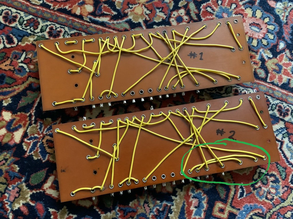
Do not worry about the layout, in the green circle, they are cathode bypass caps (C11 and C12) and coupling caps (C8 and C10) connections. The bottom right wire is HT+ from R7. They are not likely to cause a problem unless one has a poor connection or solder joint.
Good luck for the test. Alan
Good luck for the test. Alan
Tony L
Administrator
All back together. I’m just a few minutes into a very tentative power-up (one amp, only followed by the other when I knew it had come up ok), and at this point I have no buzz, crackle, distortion, explosions, fire or anything. Not counting any chickens yet, it is very, very early days yet, but maybe it was either the carbon comps or a crap joint somewhere (not necessarily mine!).
I’ll give things a far better assessment over the next few days and see if
PS I’m a bit triggered by my reassembly soldering. It is just so absurdly easy to over-heat the tired old plastic cable sheathing, so you can tell I’ve been in there now. No iron drops, knocks or anything really dumb, just some heat.
John_73
pfm Member
Sounds like a well-deserved result Tony! Will keep fingers crossed it now behaves. Perhaps it was those carbon comps then.
It's ridiculously easy to melt the sheathing. I melted the ends of two wires when I was (carefully!) desoldering an output transformer from my Stereo 20. Put me in a thoroughly foul mood for the rest of the day! Fortunately I was able to pretty well disguise it by cutting off split melted PVC end, gently heating the wire and pulling the PVC gently forward, then waiting until it cooled. Seemed to take up the space nicely. So you might be able to fix it, or alternatively use a little coloured heat shrink sleeving over the end.
It's ridiculously easy to melt the sheathing. I melted the ends of two wires when I was (carefully!) desoldering an output transformer from my Stereo 20. Put me in a thoroughly foul mood for the rest of the day! Fortunately I was able to pretty well disguise it by cutting off split melted PVC end, gently heating the wire and pulling the PVC gently forward, then waiting until it cooled. Seemed to take up the space nicely. So you might be able to fix it, or alternatively use a little coloured heat shrink sleeving over the end.
Tony L
Administrator
I gave it half an hour or so earlier, turned it off whilst I had some food, powered it up again now and no issues yet. I think the carbon comps are, I guess somewhat unsurprisingly, the most likely explanation. HiFi Collective even warn about them. I just thought they were ok as they measured absolutely perfectly. I actually bought them expecting them to be off spec and heading straight to the bin, I only fitted them as they really were absolutely bang on 3.3m. They actually measured better than the metal film (all 3.1xx, the ABs were all exactly 3.3xx). I guess that is only part of the story though. I was really starting to suspect them once the crackling started as I know that sound from guitar amps etc. I never understood the buzz at all, I still don’t, but that could have been something else entirely, and of course may reoccur.
I plan to leave things be for a month or two just to assess that I have actually fixed things properly and it is reliable. That done, depending on how obsessive I’m feeling (likely very), I may even redo all the wiring from the valve bases to the board with new if I can find some nice solid core of the appropriate type in appropriate colours. When I reassembled it I just flat soldered all bar the power and ground wiring rather than feeding it through the eyelets etc just to make it a lot easier to disassemble again if need be, so I may well view this as a ‘test’ build and really go to town later. It will certainly come apart again easily should I want to. It really depends if you can buy short lengths of that type of solid core cable. No rush, I can be unbelievably picky over very, very long time-scales though (see TD-124 thread)!
PS A huge thank you to everyone who assisted. No way would I have got here without that.
It's ridiculously easy to melt the sheathing. I melted the ends of two wires when I was (carefully!) desoldering an output transformer from my Stereo 20. Put me in a thoroughly foul mood for the rest of the day! Fortunately I was able to pretty well disguise it by cutting off split melted PVC end, gently heating the wire and pulling the PVC gently forward, then waiting until it cooled. Seemed to take up the space nicely. So you might be able to fix it, or alternatively use a little coloured heat shrink sleeving over the end.
I plan to leave things be for a month or two just to assess that I have actually fixed things properly and it is reliable. That done, depending on how obsessive I’m feeling (likely very), I may even redo all the wiring from the valve bases to the board with new if I can find some nice solid core of the appropriate type in appropriate colours. When I reassembled it I just flat soldered all bar the power and ground wiring rather than feeding it through the eyelets etc just to make it a lot easier to disassemble again if need be, so I may well view this as a ‘test’ build and really go to town later. It will certainly come apart again easily should I want to. It really depends if you can buy short lengths of that type of solid core cable. No rush, I can be unbelievably picky over very, very long time-scales though (see TD-124 thread)!
PS A huge thank you to everyone who assisted. No way would I have got here without that.