
You are using an out of date browser. It may not display this or other websites correctly.
You should upgrade or use an alternative browser.
You should upgrade or use an alternative browser.

Tony L
Administrator
Why is the mains/chassis earth disconnected?!
PS I have to admit I’d take mine in preference as I bet the Takman carbon films I used will stay in tolerance far longer than even selected and tested Allen Bradleys, same for the Russian military PIOs vs. Audio Note as they are cast metal sealed with glass, plus I retained Harold’s magic safety resistor! Obviously I’d take that one well ahead of Jez’s ugly hack-job upthread! ;-)
PS I have to admit I’d take mine in preference as I bet the Takman carbon films I used will stay in tolerance far longer than even selected and tested Allen Bradleys, same for the Russian military PIOs vs. Audio Note as they are cast metal sealed with glass, plus I retained Harold’s magic safety resistor! Obviously I’d take that one well ahead of Jez’s ugly hack-job upthread! ;-)
snowman_al
pfm Member
Moving on then...
I've thoroughly cleaned the chassis inside and out and straightened the rear section. If you look at the previous pictures with the mains fuse, you can see the angle it was at. It must have been dropped and maybe that is why all the mains input and output sockets were missing? These are tough to get back to shape!
Managed to find a couple of used 4mm speaker sockets and made them up to fit. Same with the input sockets, from a scrapped AI500 chassis. Made a small alloy cover for the outlet hole and dug out a Bulgin mains socket.


I've also 'skinned' a pair of 50+50uF caps ready for painting.

More pictures here: https://photos.app.goo.gl/CQSCCfgAw12rEv568
I've thoroughly cleaned the chassis inside and out and straightened the rear section. If you look at the previous pictures with the mains fuse, you can see the angle it was at. It must have been dropped and maybe that is why all the mains input and output sockets were missing? These are tough to get back to shape!
Managed to find a couple of used 4mm speaker sockets and made them up to fit. Same with the input sockets, from a scrapped AI500 chassis. Made a small alloy cover for the outlet hole and dug out a Bulgin mains socket.
I've also 'skinned' a pair of 50+50uF caps ready for painting.
More pictures here: https://photos.app.goo.gl/CQSCCfgAw12rEv568
Mike P
Trade: Pickwell Audio
Coming along very nicely.
I'd be wary of using 50uF in the C13 position as I fear it will stress the GZ34.
It should be fine to add a bit of extra capacitance in parallel across C12 though if you want, as this is on the other side of the 100R.
In both of mine I settled on the original value of 32uF+32uF in the C13+C12 position but then increased the capacitance in the C10+C11 position to 50uF+50uF.
Jez may advise further.
NB: There's an ebay seller who sells rubber feet that are perfect for the chassis (see my restoration thread).
Tony L
Administrator
Chassis looks good!
Are you sure you want to use 50uF? The correct value is 32uF and given good GZ34s are £100 or so and the mains transformer is already running at close to its limit I’d personally stick to the proper values.
As to feet the ones for 3-series Quad fit perfectly, same thread pattern and the physical size is exactly right.
Why is the mains/chassis earth disconnected?!
PS I have to admit I’d take mine in preference as I bet the Takman carbon films I used will stay in tolerance far longer than even selected and tested Allen Bradleys, same for the Russian military PIOs vs. Audio Note as they are cast metal sealed with glass, plus I retained Harold’s magic safety resistor! Obviously I’d take that one well ahead of Jez’s ugly hack-job upthread! ;-)
The earth wire was reconnected prior to being sold, as it belonged to a friend. I restored it for him about 20 years ago. My point for showing this is, the best results are achieved when the amplifier is sympathetically restored using parts, close too, or similar to the original parts construction. The circuit is totally original too. If you condition the carbon composition resistors, as I do, their performance and tolerance lasts a very very long time. The AB resistors were used almost exclusively in the US military equipment where reliability was paramount. Sound-wise the carbon comps will provide a smoother more open sound than the Takmans. While the Russian caps are decent (good value too), they do not perform as well sonically as some of the specifically made audio coupling capacitors do. I proved this a few years back when I restored some Flea U47 microphones that used the same Russian capacitors. The Leak "safety" resistor is maintained in this restoration and will drop off as intended if the current draw increases beyond design parameters.
Hi-FI World magazine should have a few images of my earlier restorations that I did back in the early 1990s... Most of the pics I still have are on film, so not that easy to post on the web with good clarity.
")
I already have two minty sympathetically restored ST20's but if I ever come across a knackered one which already had a butchered chassis, I'd be tempted to build it up with a choke and paint it to match the chassis so that it all looks factory.
If you do, you would only need a small value choke, preferably with a low DCR in order to maintain the correct HT voltage. Having said that the GZ34 produces very low voltage spikes compared to a silicon rectifier. A choke will help to reduce these spikes, so is probably more relevant to use on a solid-state power supply. The main purpose of using a choke with a valve rectifier is to aid in the reduction of ripple when having to use a small value capacitor to match the valve rectifier. A good well calculated valve power supply can produce stunning results.
The main problem with the ST20 is the very high gain of the circuit, typically 150mV for full output. I normally reduce this to about 800mV with no loss in sonic or measured performance. That way it is much more suited to match modern day sources that output 2 volts.
Last edited:
snowman_al
pfm Member
I think the chances of finding a Stereo 20 to modify are pretty slim these days...
No problem with a 50uF cap straight after the GZ34. The TL12+ has a 60uF+100uF in that position.
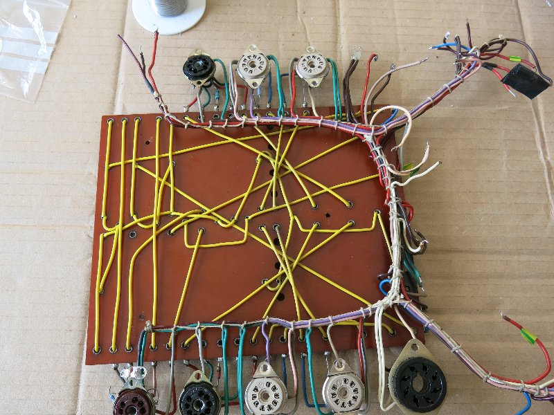
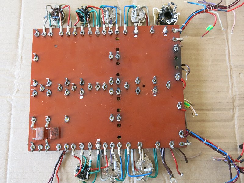
Undercoated the caps and filler plate. Repaired the missing and snapped tags, replaced the EL84 valve holders and pulled / repaired the missing and fractured wires in the harness.
Yes those are UF4007 diodes on the rectifier base.
More pictures here: https://photos.app.goo.gl/CQSCCfgAw12rEv568
No problem with a 50uF cap straight after the GZ34. The TL12+ has a 60uF+100uF in that position.
Undercoated the caps and filler plate. Repaired the missing and snapped tags, replaced the EL84 valve holders and pulled / repaired the missing and fractured wires in the harness.
Yes those are UF4007 diodes on the rectifier base.
More pictures here: https://photos.app.goo.gl/CQSCCfgAw12rEv568
snowman_al
pfm Member
Quick update...
Transformers fixed, re-taped and fitted.


Board re-mounted too.


Need a single speaker impedance selector plug or plastic cover, anyone?
Pics here: https://photos.app.goo.gl/CQSCCfgAw12rEv568
Transformers fixed, re-taped and fitted.
Board re-mounted too.
Need a single speaker impedance selector plug or plastic cover, anyone?
Pics here: https://photos.app.goo.gl/CQSCCfgAw12rEv568
snowman_al
pfm Member
@ Mike P, yes there a a few 'selectors' on ebay, but I only need the plastic cover or just one... anyone?

@ John 73, yes to protect the GZ34. Mullards are probably bomb proof(famous last words), but the Current crop of Chinese and Russian do have a few problems. The extra diodes do help and if there is a flash over or short they stop AC on the electrolytic caps... I do it as a matter of course now. The idea has been round for a long time, I think it started on the Dynaco forum as here:-

@ John 73, yes to protect the GZ34. Mullards are probably bomb proof(famous last words), but the Current crop of Chinese and Russian do have a few problems. The extra diodes do help and if there is a flash over or short they stop AC on the electrolytic caps... I do it as a matter of course now. The idea has been round for a long time, I think it started on the Dynaco forum as here:-
snowman_al
pfm Member
Moved on a little.
Painted the caps and filler plate. Could not get VW Sand Metallic paint? Settled for Ford Olympic Gold. It is a good match for the finish and the camera makes it look a bit lighter than the eye sees it.


Started to re-populate the board too.

Painted the caps and filler plate. Could not get VW Sand Metallic paint? Settled for Ford Olympic Gold. It is a good match for the finish and the camera makes it look a bit lighter than the eye sees it.
Started to re-populate the board too.
Barrymagrec
pfm Member
Even if the original Leak paint was perfectly matched at the time, different materials, different process and 50+ years would probably fade it at a different rate anyway. Gold was never the most stable of paint colours.
John_73
pfm Member
Even if the original Leak paint was perfectly matched at the time, different materials, different process and 50+ years would probably fade it at a different rate anyway. Gold was never the most stable of paint colours.
Yep. Same with the Quad IIs. Even units with close serial numbers would vary. In those days I guess these amps where really intended for mounting inside a cabinet, with only the control units being visible, so perfection of paint jobs wasn’t quite an issue as it is nowadays. As you say different materials and processes back then also.
I have a grey Stereo 20, and like the gold units there’s a difference in colour between the transformer cowls, the capacitor cans, and the main body. I get the impression on all units that the paint for the main body was properly done and given more attention, whereas the paint for the cowls was sprayed directly on without any undercoat first. It’s not uncommon to see the paint flaking off the cowls. A big chunk came off of one of mine, and it was obvious there’d been no undercoat done first to help the paint adhere.