advertisement


Keeping Linn LK boxes alive for another 20 years

dingding

DingDing
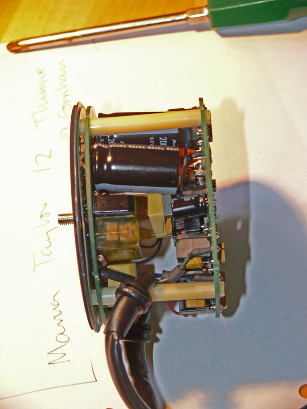
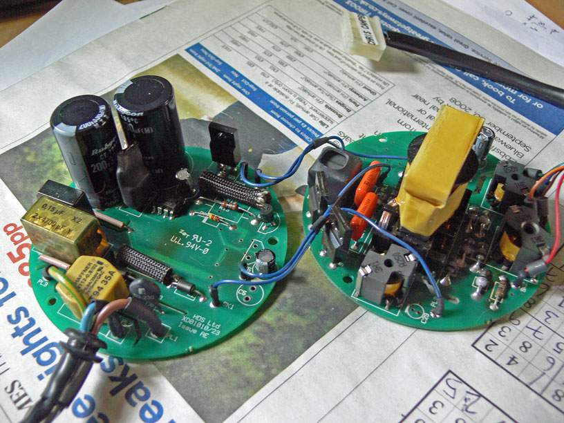
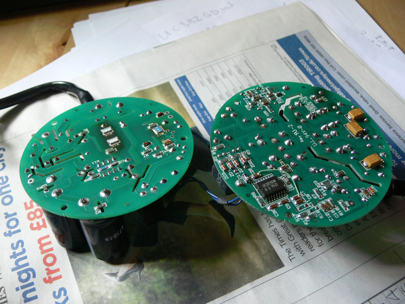
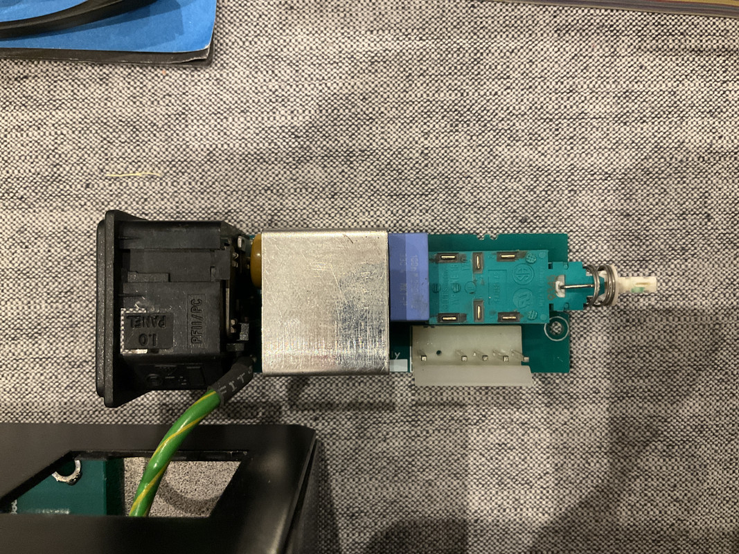
Sorry I know the Linn smps post has been done to death but I have a dead karik and numerik with the round Micky mouse power supply. They have been repaired so many times over the years so enough is enough I have decided to attempt to convert them back to toroidal transformer operation. It got me thinking that i can’t be the only one with this problem so maybe its worthwhile creating a post to throw ideas around on how to overcome these issues.

I was wondering if anyone else has done the same and if they had any details about the voltage of each colour cable from the smps and any recommendations for toroidal transformers and what rating diodes and other components are required. Maybe we could make a part list keeping things simple to follow.

I thought if I opened this post maybe it would be handy for others to use as a reference to keep the loverly old Linn Lk units running for another 20 plus years.

All ideas and advice welcome the more the better.
 
Just wondering if anyone has any ideas, I have one smps that works perfectly first time but once switched off will not come back on for hours. I have replaced all caps but now at a loss as to what could be the issue.

also if anyone has any info on how to convert back to transformer operation I would be very grateful.
 
What is the failure point of the SMPS? I know next to nothing about Linn amps, actually nothing, but in an IT context switch mode PSUs tend to be reliable and fixable things, e.g. I’ve got an early ‘80s BBC Micro that still works perfectly after a basic recap of the PSU (in fact the PSU still worked before the recap aside from the Rifa spark suppression cap blew up!). Same goes for countless PCs of all ages, the caps can dry out and fail, but that isn’t a conceptual fail of the PSU type. I’d be more inclined to try and work out why the Linn PSU fails rather than assume it needs replacement with a different type.
 
Disappointing. Can the FETs etc not be swapped to higher-rated equivalents? The caps could certainly be swapped out for better quality 105c types that should give a decent enough lifespan. I’d expect @linnfomaniac83 to be the reference point here.
 
Yes, been there, done this, and if you’re reverting back to a linear type PSU, an old Linn Direktor or room amp has the perfect transformer for the job and they’re reasonably inexpensive. Linn used the same part in lots of different products including the early Karik/Numerik, Kairn etc… now unless your units were originally supplied with transformers and later upgraded with switching supplies then you won’t have the bridge rectifiers already in place, so those will need adding.

I can send the schematic for the “round brilliant” PSU to work from, it has the output voltages listed.
 
Thank you linnfomaniac83 that would be wonderful. I have run a few tests today as it's all been off overnight and the outputs are.

9.7v DC
Blue -
Green +

Brown + 24v DC
Red 0v
Orange - 24v DC

Looking in the Karik I'm guessing I replace the resistors/caps ? In the two bridge rectifier spaces with two bridge rectifiers.
Making its fully rectified DC again.

Then connect the transformer up with the correct input pins then off I go ?
Sounds about spot on to me. I’d have to look at some detailed pictures of your units because they made some board revisions, they never actually removed the positions to fit the rectifiers but they did add some traces that bridged at least one of them out on at least one product at some point (the one that deals with the single rail 10v supply I think). On the split rail 24v supply, they fitted MOVs to prevent the large smoothing caps tripping the power supply on startup.
 
That's exactly what I have, two spaces for rectifiers one with links looks like it's the 10v side and the other with MOVs.
All makes perfect sense now.
It sounds like it should be fairly easy to convert back.
Any idea of what spec rectifiers are required ?
 
Sorry, you’re right… frosty head here today (for very good reason, high stress, tiredness, tension headache). Anyway, they need ripping out and replacing with a bridge rectifier if you’re going to fit a transformer. Beyond the rectifiers, the onboard smoothing and regulation never changed from the first transformer based units, so the smoothing caps are massively over specified for what’s needed with an SMPS. The NTCs are just there to prevent the SMPS seeing a heavy load on power up.
 
That’s great thank you so much. I’m going to give it a go as I have nothing to lose as it’s such an old unit but still reads discs and plays perfectly I can’t throw it out. Overkill for the home office but for non critical listening lk boxes are the perfect size.
Plus a great hack to keep them going.
 
Thank you linnfomaniac83 that would be wonderful. I have run a few tests today as it's all been off overnight and the outputs are.

9.7v DC
Blue -
Green +

Brown + 24v DC
Red 0v
Orange - 24v DC

Looking in the Karik I'm guessing I replace the resistors/caps ? In the two bridge rectifier spaces with two bridge rectifiers.
Making its fully rectified DC again.

Then connect the transformer up with the correct input pins then off I go ?

Good idea for a thread!

I measured my Karik and Numerik SMPS output voltages a while back in-situ under load (both late models and equipped with slimline Brilliant SMPS)

Brown +19V
Red 0V
Orange -19V
Yellow 0V
Green +10V
Blue 0V

The slimline Brilliant runs really cool compared to the earlier versions and appears to be a Linn factory made item with high quality of build and parts. Both mine are still going strong after over 20 years so no complaints if they go pop. In that event (and if I can't repair) my plan will be to build a simple outboard supply with 317/337 regs to get the voltages firm and provide a reasonably clean supply, which will be plugged into where the SMPS socket sits on the main PCB.
 
I have a round Linn power supply that powers up first time but once switched off it won't come back on. After an hour or so try again and it works fine. I have replaced the capacitors but it's still got the same fault.
Just wondering if anyone had any ideas?
 
The round supply has a starting mechanism. There is a FET on the mains board that sends about 9v to the other board until a signal comes back which causes a transistor on the mains board to turn the FET off.

The cap that routinely cooks, 47u/16v is part of the startup timing.

I have a Karik that had been in storage for many years, I brought it back out the other week, getting back into the idea of playing physical media, even CDs, and it lasted about 10 minutes before completely dying. The 47u cap was extremely sorry looking and rated at 85C. The others were all fine. I changed them all anyway. No change, PSU dead. I was checking voltages around the single FET that drives the startup voltage and it started. The volt meter was enough to turn the FET on. As there was a CD in the machine this was obvious, and a little surprising. Further poking about the circuit in this area showed that the 220k resistor that biases the Zener that is the source of the starting voltage was open circuit. Replacing this brought everything back to life. There was no external sign of trauma.

Obviously do not mess with this supply with the mains connected unless you know what you're doing. But checking the resistor values and swapping them is as safe as messing with the adjacent caps.

FWIW here are the three photos I took way back when for a thread here which still gets some reference around the internet. The photos have been preserved by others, which is nice, but these are the originals,

0.jpg
1.jpg
2.jpg


The resistor I had trouble with is R13, visible in the second picture, left board, between D2 and R12. R12 is another important resistor and can be checked from the other side of the board.
 
Just picked up a linn knekt roomamp opened it up and the transformer only has a centre tapped output so ( v+ v0 v- ) not tested the voltage yet but there’s no separate 10v output.
My guess would be 19v either way so any ideas on how to achieve the 10v Do I now need another transformer?

also I’m working on a numerik so can I keep the circuit behind the power socket inline ( it’s got the choke , caps and power switch ) or should I go from the Power connector straight to the transformer via a fuse?.
 
Last edited:
This is the part I’m unsure to bypass or leave in circuit?. I will keep the switch and fuse whatever I do but not sure what to do about the rest.
image.jpg
qh191JH9)


advertisement


Back
Top