advertisement


HMV valve amplifier

Budney

Member
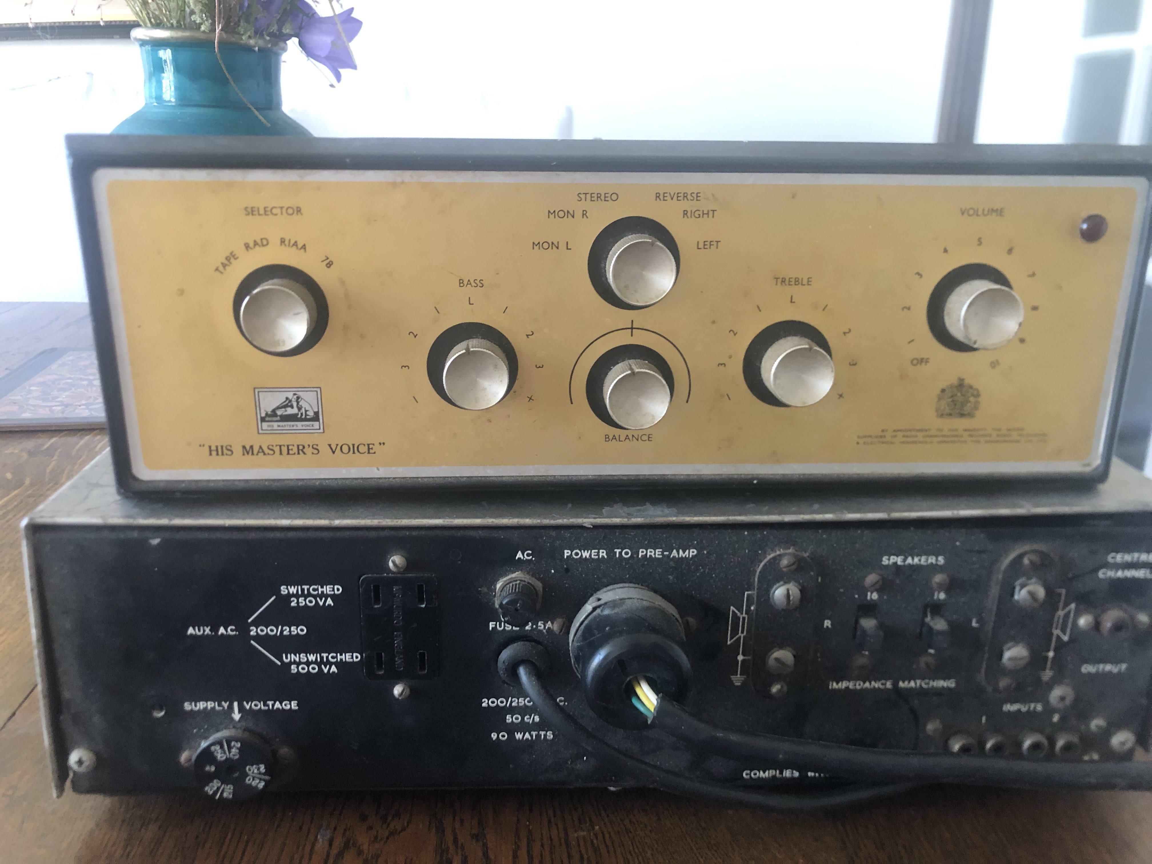
During the first lockdown I was bored and fiddling with random things, a friend of mine gave me this pre amp and power amp set, said it used to belong to his dad. I put it on the shelf at my parents at the time and just forgot about it as I didn't have access to a valve tester thanks to covid.

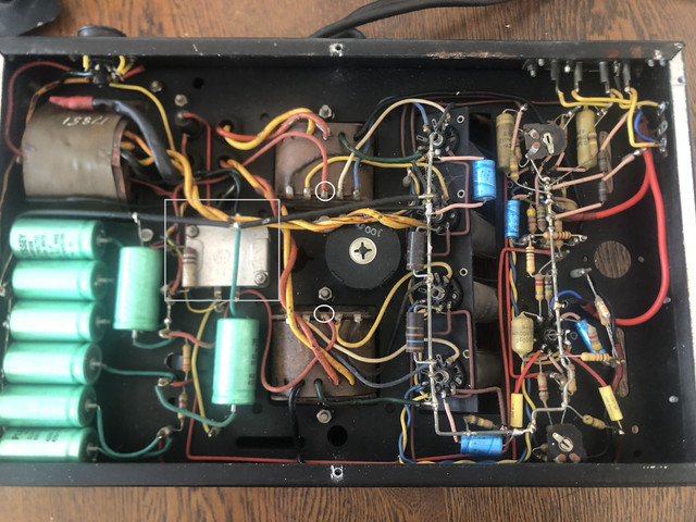
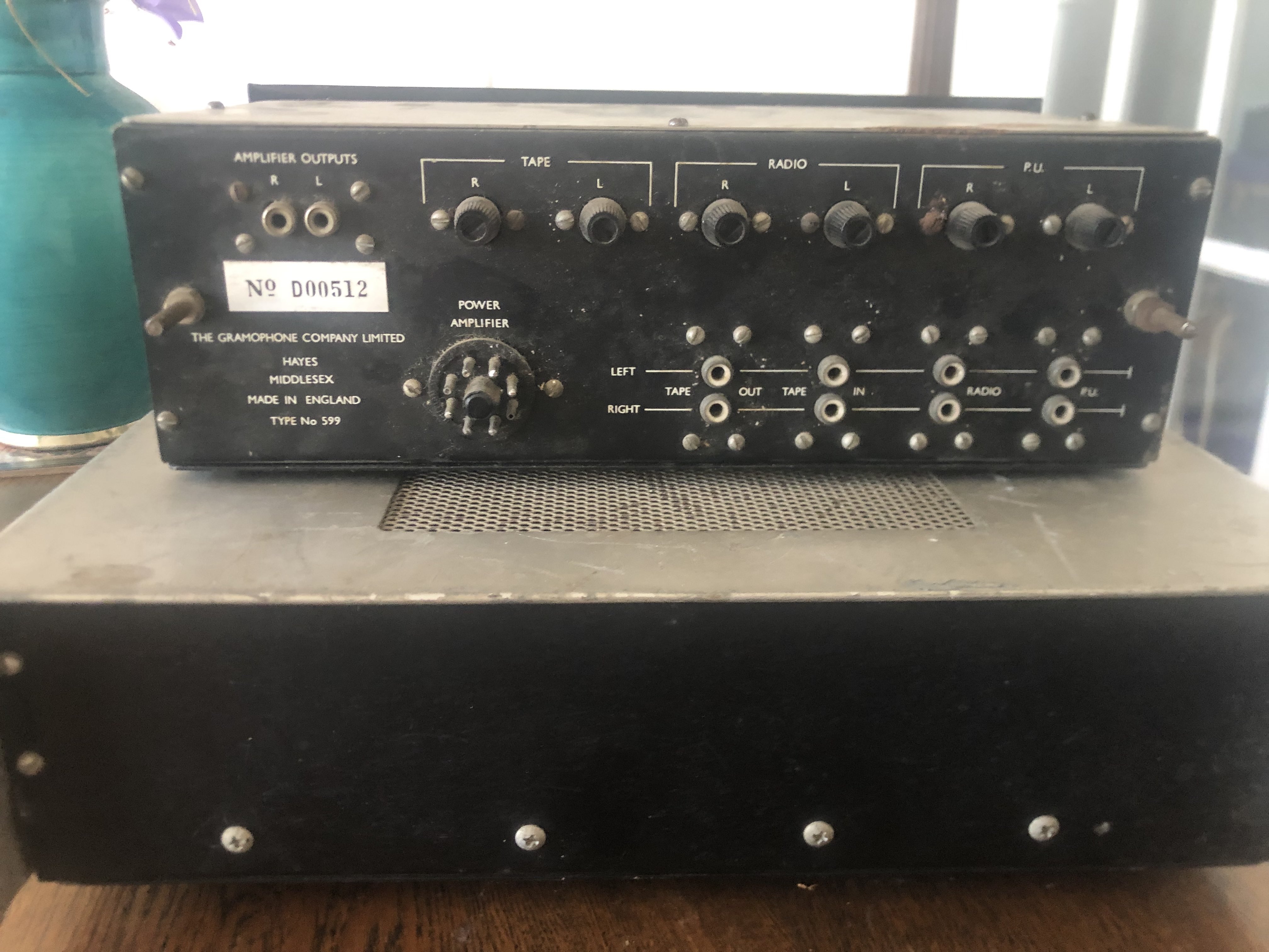
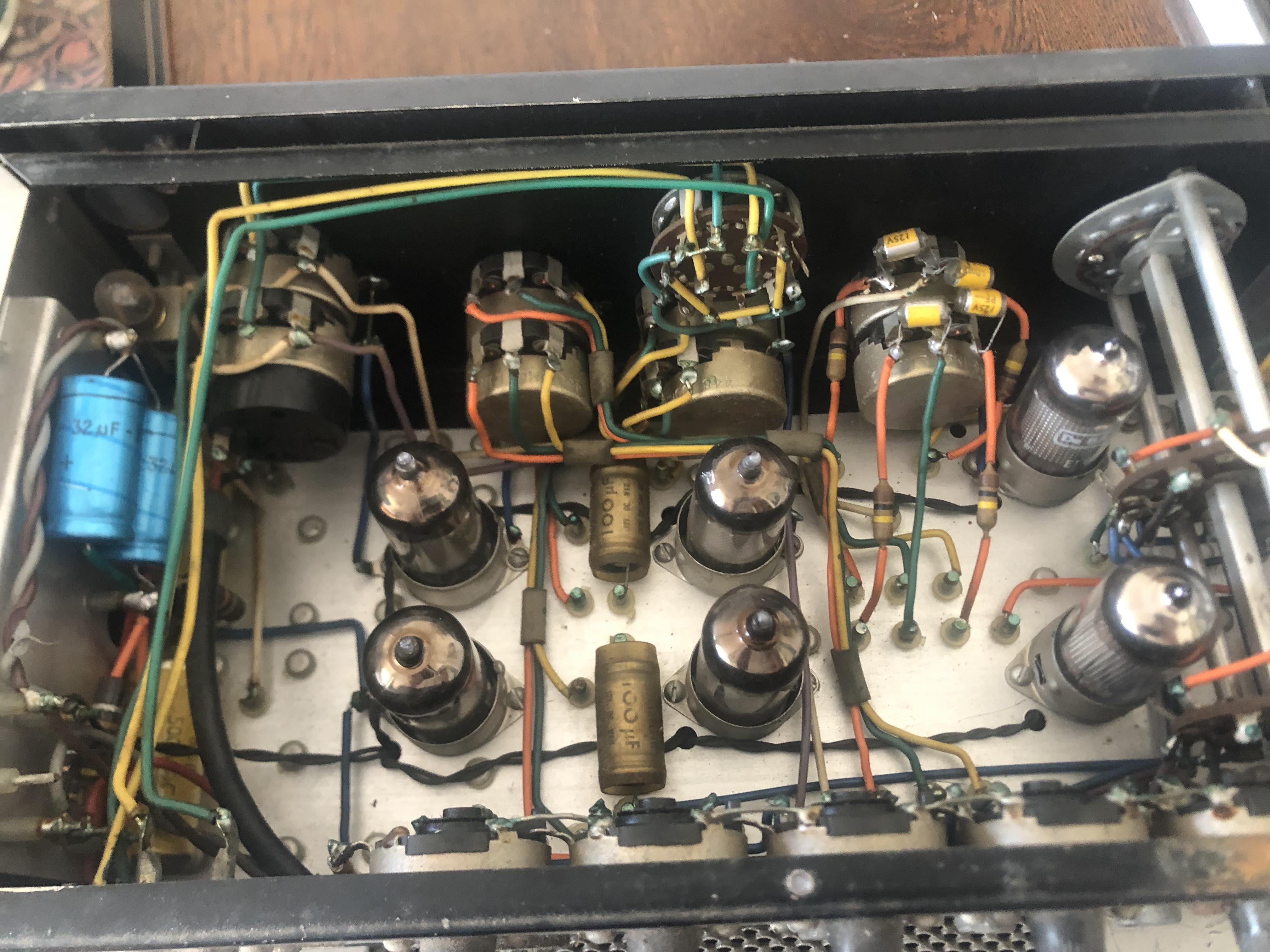
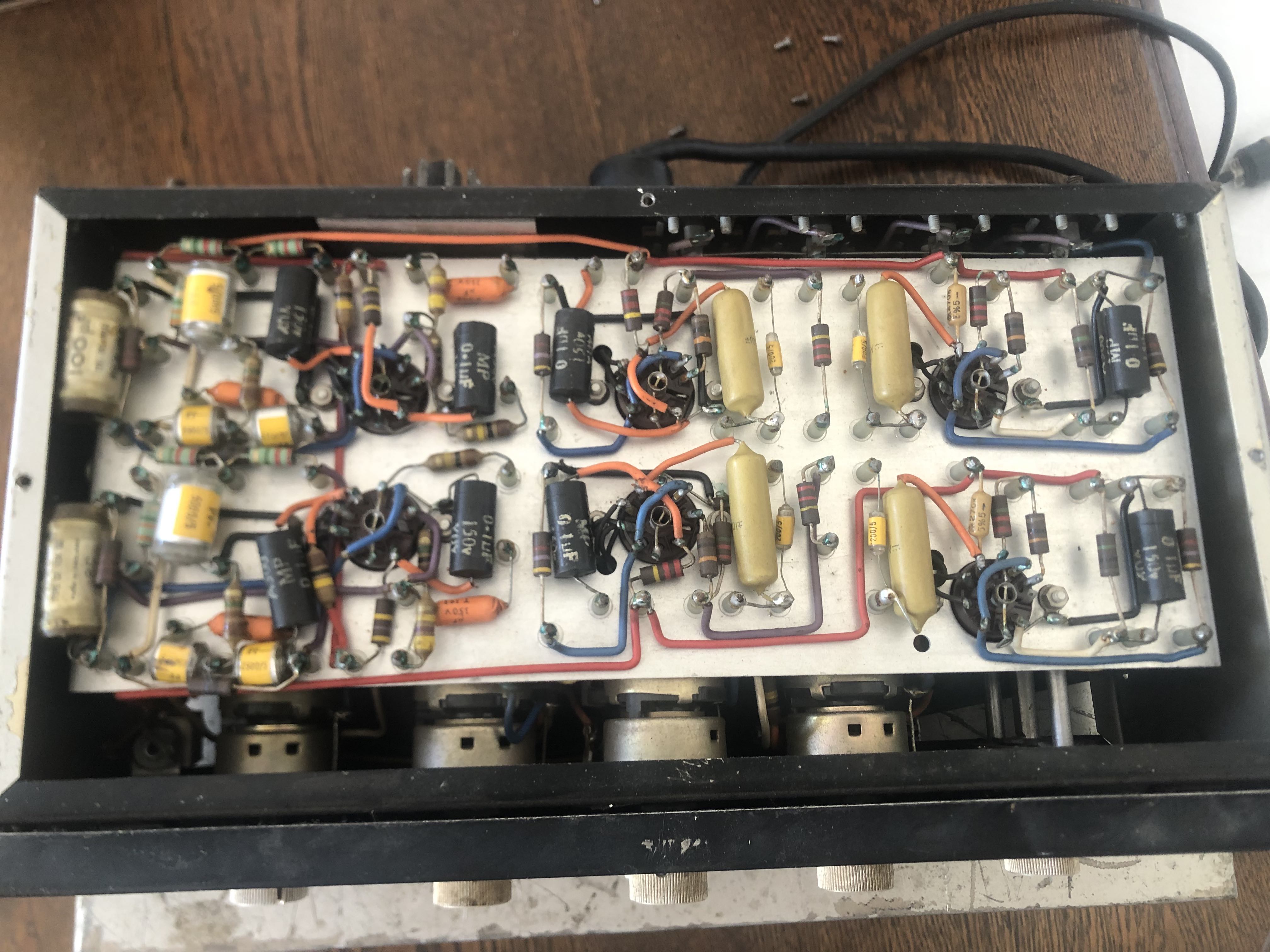
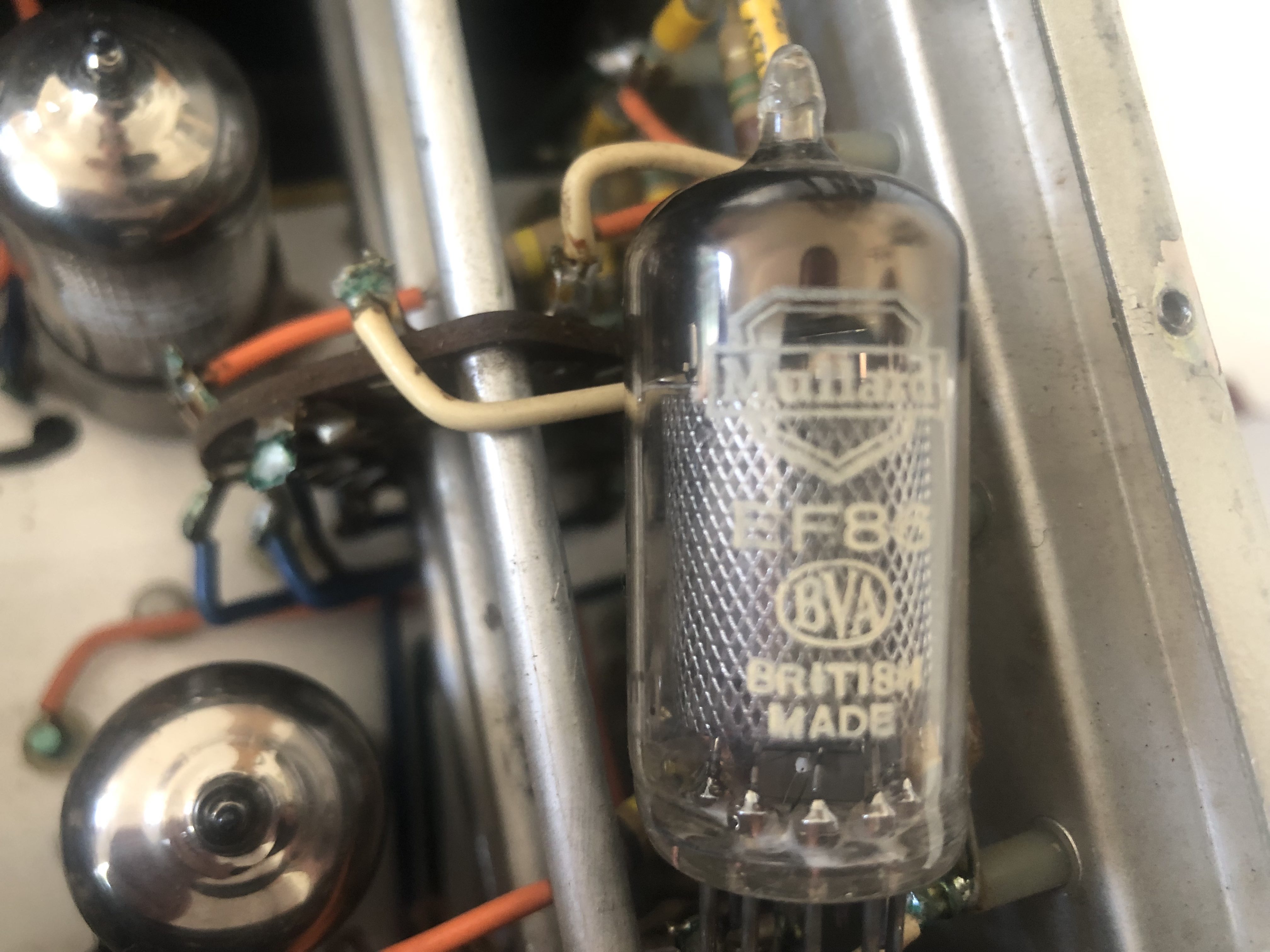
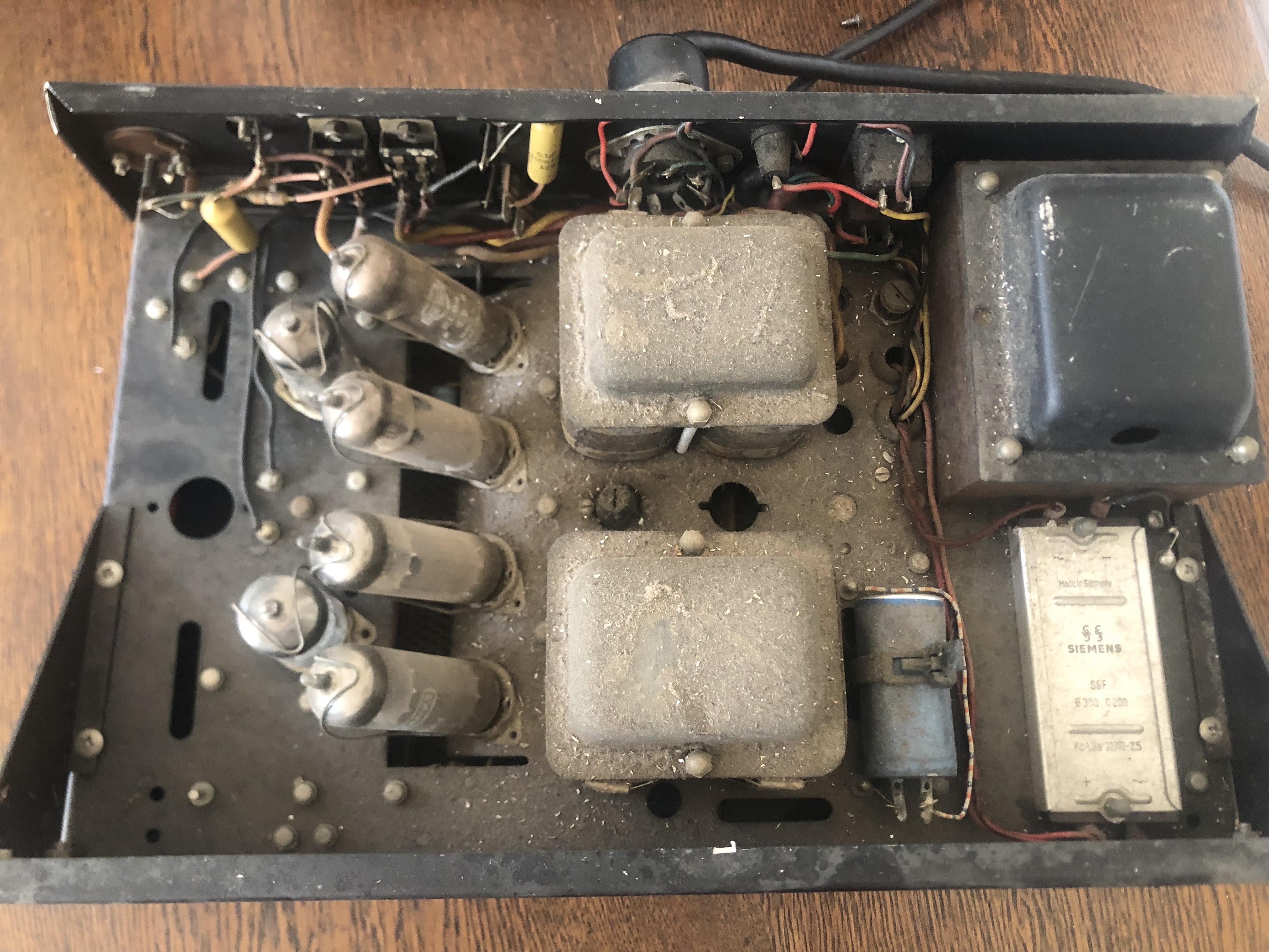
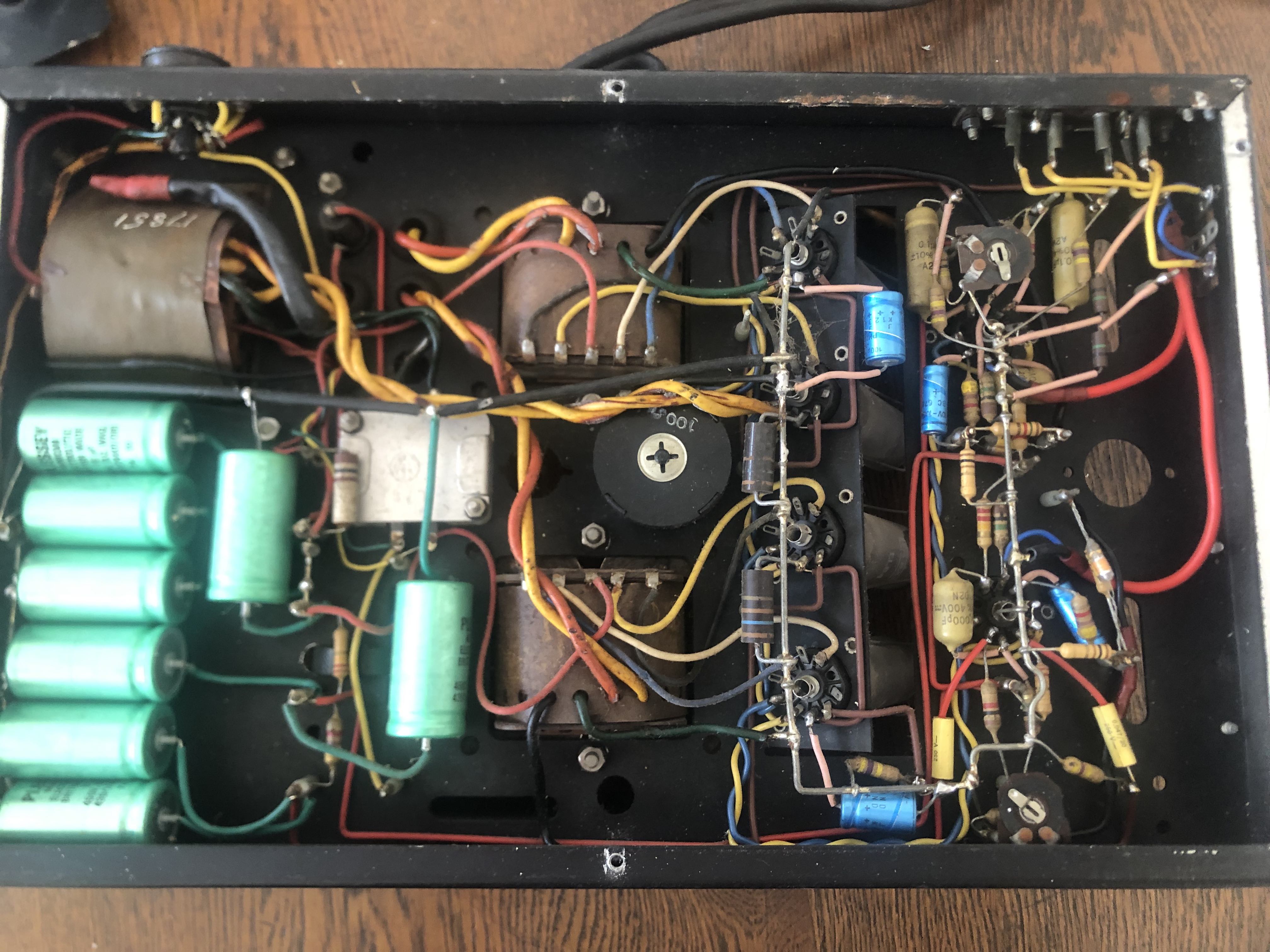
I came back to my parents this weekend and found it again, and started doing a bit of digging. I can barely find any info online, I think they are the 557 and 599 models. It has Mullard valves, but also a brand called De Banks which I've never heard of before. One channel is De Banks and the other is Mullard in both the pre and power amp, so I think someones changed them over the years perhaps. Everything else looks original, I think this is late 50s.

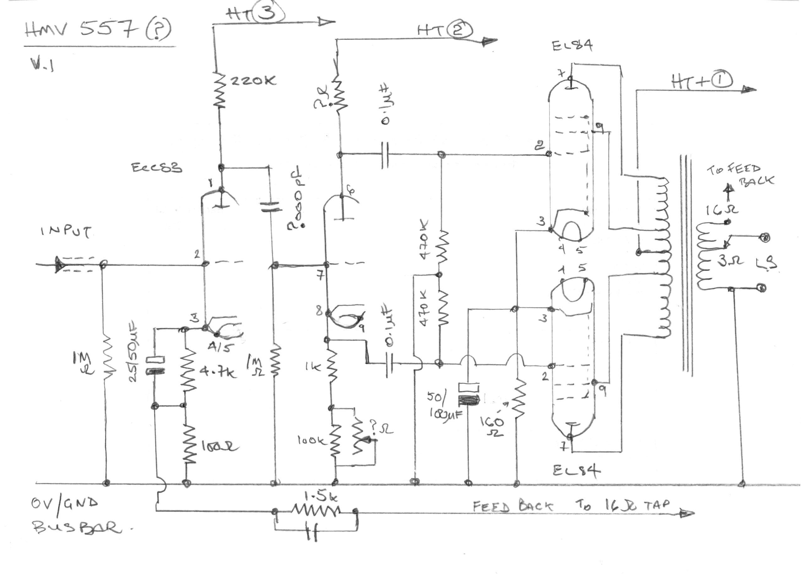
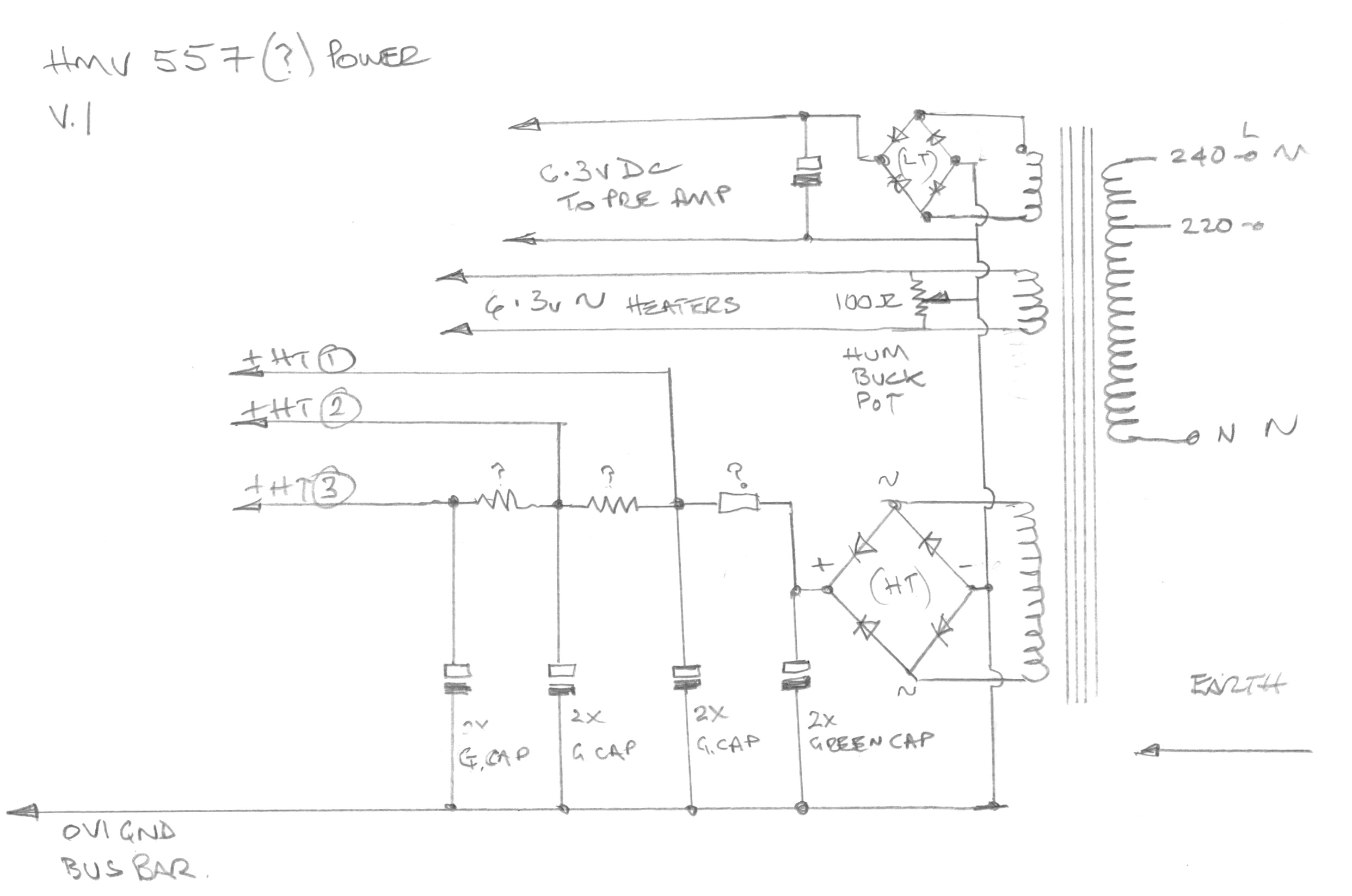
I'd like to try and use it, but with around 10w I don't have many choices for speakers. Also I think all the passives will need changing, which isn't a quick job, and since I can't find any schems I'd also be flying blind. Was thinking of using a variac to turn it on for a test, but I can't imagine it'll be functioning correctly after nearly 70 years of sitting on a shelf.

Anyone ever seen or heard these before?

paWolsG.jpg

WhG8CYw.jpg

j8wLXCI.jpg

gzFmSZY.jpg

6Z6cdBV.jpg

ItBD9YV.jpg

qVhwdkU.jpg
 
Interesting. Never seen/heard of that. The build quality looks pretty decent, a level down from Quad or Leak, but still very respectable. The PSU looks to have a selenium or other early solid-state rectifier, which is likely all kinds of dodgy by now, so I’d think carefully about how to proceed. I’d not go near power without a dim-bulb tester, and ideally use a variac. That rectifier is the thing to test first, and even if it seems to be working don’t assume it will continue to!
 
I think you may find this is very early EMi which the Hmv factory became later just look up emi pre amp and look at the control knobs for an idea. Only a Hunch at the moment.
 
A nice gift project!
Very little info about them, no obvious circuit diagrams etc. (There is stuff on the Stereoscope 555, but it does not relate unfortunately). There is some advertising too. They had various names, Clarke Smith, EMI and HMV, but the 557 and 599 parts stay the same. Audio Audio puts them as 1960 - 63.
Someone has loved them as the bright blue electrolytic caps (Philips / Vishay) are replacements. As are a couple of yellow poly caps in the power amp (bottom right of the picture.) The others are Mullard mustards so should be fine.
De Banks were a re-brander so they could be any make.
Not sure I would use the pre-amp, but if you feel inclined at least swop out all of the black Hunts 0.1uF caps and the silver 100uF electros.
Umm, a bit envious.
 
Although I'm familiar with the HMV 555 model, your amplifier is a new one on me. Certainly a rarity and I imagine, like most decent quality EL84 amps of that era it sounds very respectable. The 'De Banks' valves you mention are likely to be re-branded East European tubes manufactured in the late 1960s / 1970s.
 
From 1962
EMI one rebadged £66, HMV 556 preamp £41, HMV 557 10w stereo £31, HMV 599 control unit for 557 £12;
 
Listed in Audio Audio as 1960-1963 by Johnathan Hill (The Gramophone Co LTD)
Selenium rectifiers are not as efficient as modern recs ,so may need to reduce voltage if/when replaced
No mistaking the smell when one goes belly up, highly toxic ,dangerous fumes given off
 
I've got one of those pre-amplifiers, somewhere! Bought it with a power amplifier (6L6 based) about 30 years ago. Worked first time (even though it was very old, then). Didn't really float my boat, but it had 6 off EF86's (Philips) which obviously worked, and I'm going to use those in a phono amplifier for 78 duty.
 
So this seems like quite the little rarity! That's pleasing :)
I gather then that the first step is a ramp up test with variac to see if anything blows up, as well as running the tubes in a tester. Then replacing the electrolytics and the bridge, as well as the black 0.1. is there anything else I should be aware of? I'm not that versed on valve things, have only really worked with solid state stuff. The bridge I assume can just be some diodes? Really wish I could find some schematics.

Not sure I would use the pre-amp, but if you feel inclined at least swop out all of the black Hunts 0.1uF caps and the silver 100uF electros.
Umm, a bit envious.

Why would you not use the pre amp? I won't be using this for playing records, It will probably do bedroom duty which is just a wifi streamer from my phone so was thinking that some tubes could warm it up a bit!
 
The pre is of its day. With 3 EF86 each side it will have more noise than we accept today, but you might appreciate that. Also the streamer will probably overload it, a simple passive volume control into the power amp will be all you need. Just my thoughts, no need to follow.

Yes if you have a varic bring it up slowly and monitor the HT+ volts. (Be sure you plug some sacrificial speakers into each channel.) The red wire on the output transformers is the primary centre tap is a good point to use, circled in the picture. Look out for the temperature of the pack of green Plessy capacitors. Without a diagram expect +290 to 310 volts a full mains voltage, if the bridge and caps are co-operative.

There are 2 selenium rectifiers in there. I suspect the top one is for the HT and there is also one mounted underneath (in the grey box) which perhaps is to rectify the EF86 heaters in the pre-amp?
Yes just a four diode bridge. You can often pop them apart and replace the selenium plates with 4 UF4007s for the HT one. You normally have to add a 100 or 200 ohm 5 watt resistor in series to drop the increased volts the silicon devices give.


You need to know the valve pin numbering when testing. They are numbered from the gap and from the component side.

 
As an aside, there are a couple of pictures of HMV599s online and they have another valve installed, where your example has a blank hole. I wonder if there was more than one type of 599?

 
Here you go, HMV 557 circuit reverse engineered from what I /we can see. Please everyone chip in if you see an error or have a suggestion.
I cannot see how mains earth or the chassis is connected to the bus bar.
Also the circuit matches the bottom half of the picture, the ECC83 pin numbers swaps round at the top half.
Better pictures might help and you will get a feel for it (not literally I hope) as you go on. Alan


HMV557-PSU-001.jpg
 
I'd be inclined to replace the 'common' 160 ohm resistors with individual 330 Ohm types for each cathode, you'll need a couple of extra decoupler caps too (50 to 100 uF).
My guess on the coupling cap is most likely 47nF.
 
Have a look at the 'top' section where the coupling caps are 0.1uF mustards. Some one has replaced them with 0.047uF poly caps for the 'bottom' section (?).
This is obviously a pruned down version to the EMI unit, common cathode resistor, no grid stoppers etc. and removal of an ECC83...
I cannot find a component side picture on the web to compare.
 
Wow thank you so much! That's such a great help. Can't believe you did that from just photos :eek: The bus bar has a small black wire going through connecting to the chassis on the other side. The extra hole does look like it should be for another tube but there's no evidence that there was ever anything installed there. There is also another hole for a hum bucker, so perhaps they would be related? Also it seems like the setting for speaker impedance is either 16 or 4 which seems odd, is there any way to set it to 8?

Is it worth me trying to find some mustard caps to get it back to the way it should be? How do you think this would compare to the EMI with the extra tube?
 
If it was mine then I'd definitely restore the mustards for aesthetic and originality sakes.
Sadly these don't seem to be settable for 8 Ohms so you'll have to run it at the 4 Ohm setting.


advertisement


Back
Top