advertisement


hackernap advice thread

Yes, I'm with Alan on the importance of the input cabling being up to scratch.
I had a similar issue when testing one of my builds where there their was a break in the screen mid cable
I was lucky and killed the power before any permanent damage
This is one reason why I prefer a locking DIN plug, but they are not everyone's cup of tea

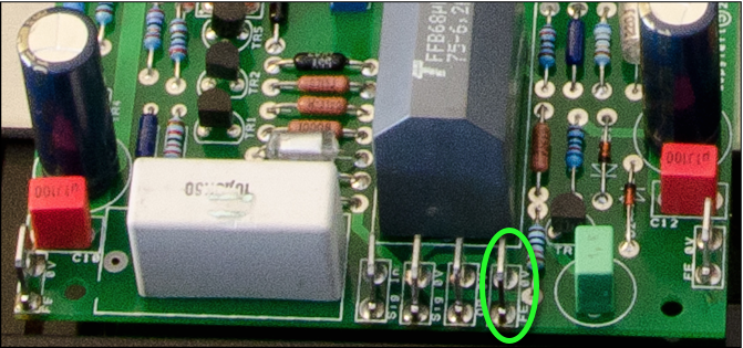
It may also be worth checking Q1, TR4, TR5 and C3 as I think they are in the path back to the FE positive supply that was dipping under load

Good luck with getting it working again, it's worth it for the enjoyment that these amps give :)

Mark
 
Few years ago I was not so lucky and an earth problem led to the demise of a magneto planar tweeter.
Entirely my fault and the feeling of complete foolishness lingered for days! Replacement was painful on the wallet and rebalancing the speakers took ages as direct replacements were not available.
Live and learn.
Cheers Andy.
 
Ordinarily there would be a wire from the point circled, below, to the 0V star of the front-end regulator:

CQoOifC.png


This is important because it is here - and here alone - that both the front-end and output stage 0Vs are tied together. However in your configuration the 0Vs are tied together at the 0V of the transformer, which negates the requirement for the aforementioned wire to be installed. This is not something I've ever tried and have never seen anyone do. It's definitely not how the HackerNAP was designed!

The idea is to keep a starred 0V reference nailed to the HackerNAP, where all the important 0Vs are joined: front-end 0V, output stage 0V, and signal 0V. It's the only place they're all joined. In your amp there's a star at the HackerNAP PCB and another star at the transformer. I'm not sure that this is a good thing, however the only way I can think of fixing it is by using a different transformer. Anything else is... unsupported!
 
Thanks, I realise the default design is for two transformers but would like to use these if I can, I just need to work out the best grounding scheme I can use in this implementation. Would creating a star point at the input ground be the best way, by running a single wire from the transformer 0V to HackerNAP input gound, and then another connection to each of the HackerCAP and reg boards?
 
Many thanks Alan, I'll try that and probably a couple of other places for the star connection to see which is the quietest.

Unfortunately I don't have room in the case for two 50VA front-end toroids, and the ones I am using are H&F which don't buzz at all, I am sure it will be fine, I just need to find the best ground configuration.
Hi David
I found that the transformer or Rectifier end of the Cap6 is noisy, OK for the speaker return but the output end of the Cap6 is the quietest place and you have multiple Ground connections there, even so I still had to put 2 cables into a single spade connector as there are quite a few ground connections on the board.
They are cracking amps so well worth the effort IMO

Best
Alan
 
I found a slight improvement by taking the Velleman ground with the speaker return back at the rectifier end of the cap bank
 
Hi all i've replaced my blown components and have the hackernap on the test bench. PSU voltages are good (+/- 55v front and back).

Bias is behaving itself - stabilising to 3.3v over 30mins.

However the DC offset is at 70mV. Do i need to change R15 as suggested elsewhere in this thread? R15 is currently the recommended 680R, so should i put 2 in series to hopefully give 35mV? or something else? or is 70mV fine?

cheers my dears...
 
Doniker

Ideally the output should be a few volts lower than the front end but it will still work fine

Bias should be 3 - 5 milli volts?, is that a typo if its volts then readjust
DC offset @ 70mv is still OK but I would start being concerned if it keeps going up
What feed back cap are you using as itsmore likely to be that or the relationship between TR1 TR2 than the resistor R15

Alan
 
Thanks for the input Alan,

yes typo - it is stable at 3.3mV. DC offset is stable now at 63mV.

Sorry mate i don't know which is the feedback cap?

I stuck close to the recommended transformer sizes (OP@ 36-0-36 300VA and FE@ 42-0-42 50VA) and after on-board FE regulation they come in almost exactly the same (+/- 55V). Seems fine so far. What problems could this cause?

I have tried it and MUSIC! It flatters my stunt speaker wonderfully!

Now for the other channel and an attenuator...

cheers
 
I stuck close to the recommended transformer sizes (OP@ 36-0-36 300VA and FE@ 42-0-42 50VA) and after on-board FE regulation they come in almost exactly the same (+/- 55V). Seems fine so far. What problems could this cause?

This should be no problem. Your output transformer winding is 1V higher than the usual 35 V so you get a slightly higher output voltage. Enjoy :)
 
Thanks for the input Alan,

yes typo - it is stable at 3.3mV. DC offset is stable now at 63mV.

Sorry mate i don't know which is the feedback cap?

I stuck close to the recommended transformer sizes (OP@ 36-0-36 300VA and FE@ 42-0-42 50VA) and after on-board FE regulation they come in almost exactly the same (+/- 55V). Seems fine so far. What problems could this cause?

I have tried it and MUSIC! It flatters my stunt speaker wonderfully!

Now for the other channel and an attenuator...

cheers

Great stuff glad its working and well done BTW ;)

The feed back cap is C2 if its leaky it can give you high DC offset
There should also be a 10% difference between TR1 & TR2
Re the front end voltage if its a few volts higher than the output you will get maximum output from the amp if it is the same or lower there will be a marginal drop but its not a big deal really.

Alan
 
Thanks again for the input.

I'm using the recommended c2 - big gray block 68uF / 6.3V Tantalum.

The transistor hfe difference thing came in handy for the 2nd board - it had dc offset of 120mv. I replaced TR1 and TR2, though TR1 is only about 2% bigger. Now it is 45mv.

So i have one channel 63mv and one 45mv. They both sound good in mono but is this difference a problem when i combine them into a stereo pair?

Thanks again
 
Cheers Hacker. I tried to send you a PM but your inbox is full so i'm typing here instead.

I'm running them with PSUs i have prototyped on veroboard for now - the ground is a little noisy. As such i'm keen to get my hands on the CAP boards from you. I'm already planning to build at least one more amp so i'm after some amp boards too if you have them?

I hope your house move is going to plan. Apologies for not quite waiting until Feb - i'm quite excited is all!

many thanks
 
A week today we sign on the dotted line! Maybe a week after that I'll have found/unpacked my electronics stuff and will be able to send some your way. I'm pretty sure I've got a couple of spare NAP boards, I'll pop some in the post for you with the CAP boards.
 
Just as a discussion topic - I use SMPS with my Connex class D amps, they are small and cool and are very well regulated as class D puts 100% of supply ripple / noise onto the audio output (I think). How about SMPS for the Hackernap? I use the Connex SMPS600RxE and I am sure it can be configured for the HN voltages. It would be smaller, lighter, cooler, cheaper than the conventional traffo approach and masses of power

Any thoughts? Phil


advertisement


Back
Top