
You are using an out of date browser. It may not display this or other websites correctly.
You should upgrade or use an alternative browser.
You should upgrade or use an alternative browser.
For want of a better name: the HackerNAP board
- Thread starter hacker
- Start date
- Status
- Not open for further replies.
cromodora
foshfishfie
I was going to go down the NCC200 route, why should I go this way rather than with Avondale?")
This is like the NCC200 plus something we'd like to try.
Onboard regulation of the front end.
Carl
What's the VBE configuration. Can you post a schematic ?
BTW I think there are several areas on the layout where the gaps could be widened. Part of Les's version (upgrade ?) was an optimal board layout.
Also I hope everyone is aware they are going to have to come up with a new power transistor mounting/heatsink arrangement.......and these won't be an easy plug and play in existing Naim amps anyway.
Also Ceds PA design has several features that could be incorporated.....
Sorry Carl if I'm pissing on your parade....but I've been down some of this road already (as you know).
cromodora
foshfishfie
I hope Carl says no. I would be embarassed to ask this of him.Will you be testing the board for stability and optimal compensation Carl? Thanks.
Here's why..
Carl is trying out this idea.
He is offering us boards to join him in trying this idea.
We think it should work after all it is based on the proven ncc cct.
At 5 bucks a pop, I don't feel I am paying enough to ask for a fully developed and tested board. Just a ticket to join the ride and see where this leads.
Carl
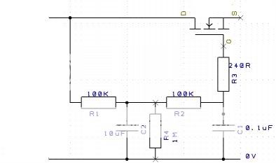
What's the VBE configuration. Can you post a schematic ?
It's an unmolested PigletsDad FET-based VBE:
midcm1 said:BTW I think there are several areas on the layout where the gaps could be widened. Part of Les's version (upgrade ?) was an optimal board layout.
There probably are. Which areas give you particular concern? I'll try and address the issues but no promises.
midcm1 said:Also I hope everyone is aware they are going to have to come up with a new power transistor mounting/heatsink arrangement.......and these won't be an easy plug and play in existing Naim amps anyway.
I did mention that earlier in the thread. I'll make sure to update the 1st post to reflect that, too. I don't want anyone thinking that this will be a drop-in replacement for NAP or NCC modules, cos it won't.
midcm1 said:Also Ceds PA design has several features that could be incorporated.....
Please let me know what they are and where they're likely to be squeezed onto the current PCB layout
midcom1 said:Sorry Carl if I'm pissing on your parade....but I've been down some of this road already (as you know).
Piss away
The voice of experience is always welcome.Can I have a little bag of the magic pixie dust you mention? Also will it give me a better sound without soldering? ;-)
Ten quid from my mate Dave down the pub.
Will you be testing the board for stability and optimal compensation Carl? Thanks.
Nope. I'll be testing it to make sure that it works for me. In fact this board is exactly my current configuration, just not all on one PCB.
Anything else is left as an exercise for the buyer. I will be ordering a few samples for test purposes before committing a bunch of people's money, but basically you're on your own with no guarantees other than "you will receive the boards you pay for".
If you're not comfortable with this, I understand completely and anyone is free to retract their interest with no hard feelings. These boards are for fun and experimentation! If you want a stable, known-good design then I suggest buying NCC200s from Avondale.
I hope Carl says no. I would be embarassed to ask this of him.
Here's why..
Carl is trying out this idea.
He is offering us boards to join him in trying this idea.
We think it should work after all it is based on the proven ncc cct.
At 5 bucks a pop, I don't feel I am paying enough to ask for a fully developed and tested board. Just a ticket to join the ride and see where this leads.
I can't argue with that!
Cheers,
Carl
Carl
I presume from your PCB diagram that TR9 and TR10 are the power output transistors. In which case would Sanken 2SA1216 (PNP) and 2SC2922 (NPN) MT200 type be suitable. It just happens that I have a set that I salvaged from an old Audiolab amp. I was wondering if I would ever get to use them. This would be ideal.
I presume from your PCB diagram that TR9 and TR10 are the power output transistors. In which case would Sanken 2SA1216 (PNP) and 2SC2922 (NPN) MT200 type be suitable. It just happens that I have a set that I salvaged from an old Audiolab amp. I was wondering if I would ever get to use them. This would be ideal.
I'll take 4 boards.
Many thanks
Ronald
PS:
whats about a multi fed regulation?:
http://www.pinkfishmedia.net/forum/showpost.php?p=310314&postcount=253
http://www.pinkfishmedia.net/forum/showpost.php?p=310797&postcount=257
Many thanks
Ronald
PS:
whats about a multi fed regulation?:
http://www.pinkfishmedia.net/forum/showpost.php?p=310314&postcount=253
http://www.pinkfishmedia.net/forum/showpost.php?p=310797&postcount=257
Carl
This is kind of where Ced was coming from with multiple regulation only using a single BJTs instead of FETs. I guess this is getting more complicated though.
This is kind of where Ced was coming from with multiple regulation only using a single BJTs instead of FETs. I guess this is getting more complicated though.
I'll take 4 boards.
Many thanks
Ronald
PS:
whats about a multi fed regulation?:
http://www.pinkfishmedia.net/forum/showpost.php?p=310314&postcount=253
http://www.pinkfishmedia.net/forum/showpost.php?p=310797&postcount=257
Nope. I'll be testing it to make sure that it works for me. In fact this board is exactly my current configuration, just not all on one PCB.
Anything else is left as an exercise for the buyer. I will be ordering a few samples for test purposes before committing a bunch of people's money, but basically you're on your own with no guarantees other than "you will receive the boards you pay for".
If you're not comfortable with this, I understand completely and anyone is free to retract their interest with no hard feelings. These boards are for fun and experimentation! If you want a stable, known-good design then I suggest buying NCC200s from Avondale.
Understand where you are coming from, and my question wasn't at all meant in any negative sense. I do think it's best though that people are aware that there is no guarantee that it'll work optimally without some playing with first.
We think it should work after all it is based on the proven ncc cct.
It is indeed, but the layout is new, and layout will have an effect on the correct compensation for the amp
stackowax
pfm Member
Nope. I'll be testing it to make sure that it works for me. In fact this board is exactly my current configuration, just not all on one PCB.
Anything else is left as an exercise for the buyer. I will be ordering a few samples for test purposes before committing a bunch of people's money, but basically you're on your own with no guarantees other than "you will receive the boards you pay for".
If you're not comfortable with this, I understand completely and anyone is free to retract their interest with no hard feelings. These boards are for fun and experimentation! If you want a stable, known-good design then I suggest buying NCC200s from Avondale.
This may be an impossible question to answer but here it is: what level of technical expertise should we have and what sort of test equipment should we have access to to make a reasonable go at this project?
If there is a BOM to tell me what part to put where, I can do that (usually). And I can solder. I can also measure DC at the output, adjust voltage across emitter resistors (at least on a NAP). But anything beyond that, things get more then a little fuzzy for me. Am I getting in over my head with this thing?
cromodora
foshfishfie
This may be an impossible question to answer but here it is: what level of technical expertise should we have and what sort of test equipment should we have access to to make a reasonable go at this project?
If there is a BOM to tell me what part to put where, I can do that (usually). And I can solder. I can also measure DC at the output, adjust voltage across emitter resistors (at least on a NAP). But anything beyond that, things get more then a little fuzzy for me. Am I getting in over my head with this thing?
Of all diy projects, an amp is the most tricky to build.
Seasoned bodgers with scopes and sig gens may get stumped halfway by a dud part while a newbie with only a cheap iron blithely goes on to complete a working amp just following a sketchy schematic with instructions in Chinese.
cromodora
foshfishfie
Carl
I presume from your PCB diagram that TR9 and TR10 are the power output transistors. In which case would Sanken 2SA1216 (PNP) and 2SC2922 (NPN) MT200 type be suitable. It just happens that I have a set that I salvaged from an old Audiolab amp. I was wondering if I would ever get to use them. This would be ideal.
2922 will fit and is actually the original trannies on CB NAP140.
You'll need 4 however and remember to salvage the insulating pads too.
They are hard to get/costly new.
- Status
- Not open for further replies.