advertisement


Fixing a Thorens BTD 12S Tonearm

awl

pfm Member
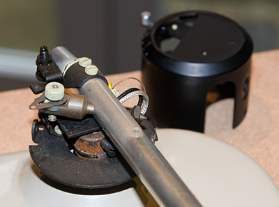
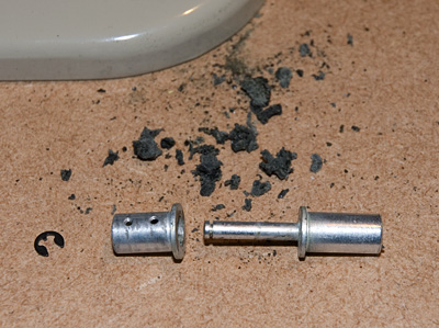
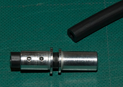
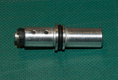
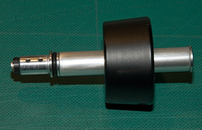
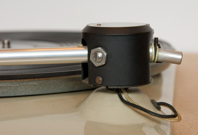
I am trying to renovate a BTD 12S Tonearm on a recently acquired Thorens TD135. The condition of the turntable is very good - I suspect it hasn't seen use for many years and so there are a number of issues with moving parts, including the arm. The counterweight stub is held in place with a now perished rubber coupling, and the counterweight now sags at an alarming angle to the rest of the arm. So the first thing I need to do is replace this coupling. To do so I need to undo two screws on the end of the arm, but these aren't easily accessed without dismantling more of the cylinder that covers the bearings and other bits. Here are some pictures:

_AWL2279.jpg


_AWL2286.jpg


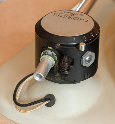
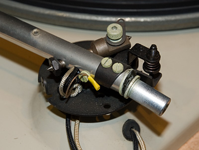
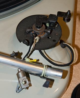
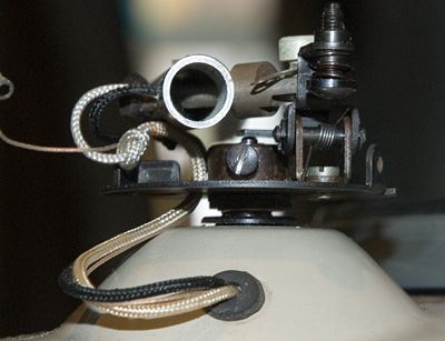
I've removed the aluminium top plate and this gives a bit more access to the inside workings, but still not enough to get a screwdriver on the two screw heads:

_AWL2287.jpg


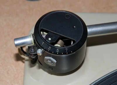
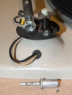
I've downloaded some drawings of the arm from Vinyl Engine and other sites, but none seem to show how to access these two screws. Can anyone with experience of this arm or others like it suggest what I could try? Which screws to undo and just as importantly which ones I should leave alone!

I suspect that the bearings on the tonearm could also do with some fresh lubricant and any advice on how to go about this (and with what) would also be greatly appreciated.

Andrew
 
Hi Andrew, to access those screws you have to remove the arm tube from the housing. This is fairly easy to do on later arms without the built in arm lift mechanism you have- you just have to back out the vertical bearings after slackening the nuts and removing the cylindrical housing cap from the base plate having removed the 2 fixing screws, then unhook the VTF spring from the tag on the arm tube. Yours would probably involve a little more dismantling to clear the lift mech- not sure what that involves but it might be obvious when you get to it.
Whilst you have the arm tube free of the housing, check the vertical pivots as they have been pitted on all the arms of that family I've dismantled. I remove the axle from the arm and spin it in a lathe (drill chuck would do) and dress the conical points with a water of ayre stone or fine wet and dry papaer to remove the pits and polish the surface.
The replacement rubber bush is not available AFAIK but you can get a complete suspension unit incl. the metal parts for a huge sum from schopper.de. Aternatively you might try bodging it somehow or cement the 2 metal parts permanently with epoxy, use an EMT stub if it's not too long or DIY something like I did from plastic or alu if you have access to a lathe.

Hope that helps,
Mark
 
I have no experience whatsoever with these arms, but looking at the picture would it not be possible to bodge something with a rubber tap-washer and a little glue, i.e. slit the washer half way, put a little glue on both surfaces and slide it in?

Tony.
 
Thanks for the responses. Tony, I think I see what you mean, but the sagging stub is not loose - the perished rubber has set solid so I can't even lift it back to horizontal without force. It really needs to be dismantled, cleaned out and replaced with new rubber. My plan is to see how it comes apart and try to replace with some rubber tubing, or perhaps rubber washers as you suggest.

Mark, your post is very helpful although I'm a bit daunted by the prospect of a total strip down. Can I just check I've interpreted the procedure correctly?

_AWL2283a.jpg


I should first slacken the nut (which I assume is a lock-nut) A, then back out the bearing (on both sides), and then remove the two housing fixing screws (B).

Is it straightforward to reassemble the vertical bearings and get the tightness right I wonder? I think I've just got to give it a go and hope springs and other small parts don't fly in all directions.

I should add that I have all the parts missing from the photos - i.e. the counterweight, stub and long fixing screw.

Andrew
 
Hi Andrew, yes you got it- not sure how the lifter arrangement is inside the cap and it would be interesting to see a pic when you get that far. Re-adjusting the bearings is just a matter of carefully removing the play without applying any pressure/pre-loading, by feel and trial and error. Lock one side in correct position and adjust other. It's quite straight forward really but make sure you do it once the cap is fitted back on the base plate as otherwise the adjustment will likely loosen. Don't overtighten the locknuts- just nip them up enough to lock the bearings in place
Mark
 
Here's an update:

_AWL2294.jpg


Removing the vertical bearing 'ends' and the cover was straightforward enough and to the naked eye the vertical pivots look in good condition. Elsewhere there's some corrosion in evidence which probably points to less than ideal storage conditions.

_AWL2291.jpg


_AWL2296.jpg


The arm-lift mechanism operates through the centre of the horizontal bearing. When it's in the 'up' position there's a significant amount of friction in moving the arm horizontally; this only goes when the arm-lift lever is completely lowered. I'm not convinced this is how it's designed to work, but once freed the horizontal bearing is easy and smooth as I'd expect it to be (and of course, as it needs to be). [Edit: Further reading indicates that this is indeed how it's designed to work, apparently to make accurate cueing easier, although I'm till not convinced it's a great idea. It does explain why I wasn't able to cure it though!]

_AWL2298.jpg


I undid the two arm stub screws and was able to pull out the stub (in the foreground of the last picture), however the sleeve which runs into the arm tube itself does not want to budge. This is going to make cleaning out the old rubber very difficult and I'm not sure of the best way to proceed. I'm not keen on un-wiring the arm tube to release it completely but without doing so would make the use of any solvent on the old rubber tricky. Will have to give it some more thought...

Andrew
 
Got it!

_AWL2300.jpg


I managed to remove the piece from the end of the sleeve by careful use of pliers and a piece of cloth to protect the lip. Everything here is aluminium and very easy to damage. The remains of the rubber can be seen all around - it had disintegrated, but had also stuck to the metal surfaces.

_AWL2303.jpg


Now I need to find some suitable tubing to replace the old rubber - anyone have any suggestions of where to source?

Andrew
 
I am not sure of tube thickness. A suggestion rubber part from valve intertube the valve pice of rubber. Another suggestion cable sleave. Maybe blue tack as well as a suggestion.
 
Contact a couple of O-ring suppliers with the inside diameter of the aluminium sleeve plus a few microns. Purchase a minimum length of cord stock, cut to length, freeze it, and then drill out the center such that a snug fit with the end stub pin is the result (this latter step may require a few attempts to get just right).

Craig
 
Thanks for the suggestions. I have ordered short lengths of three types of hose - rubber, silicone and neoprene and hope one of these will be just right. Once in place I'll then see if adding an O-ring or two will help.

Andrew
 
The tubing arrived in the post and the neoprene turned out to be a very good fit. It was hard work to get it into place, but any easier and it would probably not have been the right size or performed properly.

_AWL2305.jpg
_AWL2310.jpg


And here is the finished connector with the arm stub and counterweight:

_AWL2311.jpg


It's now mounted again on the arm and is looking and working as it should. I'm off to do some plinth building now...

Andrew
 
Looks perfect. The plinth build deserves a thread of it's own too. The TD-135 tends to get overlooked due to it's bigger brother, but I bet it's a great sounding deck and it certainly looks cool.

Tony.
 
Hi there, I am just attempting this repair and didn't look hard enough at where the spring (which I think is the bias) was attached to, can you help?
 
Refitting the spring is a bit fiddly.

_AWL2294.jpg


On the left of this picture you can see a thin plate with a hole at its end. As you lower the housing back into place, you need to get the end of the spring to pass vertically down through this hole. Make sure the spring is fully backed off - i.e. set it to its minimum setting.

It's actually the spring which is used to apply the vertical tracking force to the stylus after the arm is balanced (with the dial set to zero). There's no provision for setting bias on the BTD 12S.

Hope that helps, Andrew
Hi Andrew,

Thanks for that, that's a big help. Everything is in pieces at the moment waiting for spares to arrive so I have taken the opportunity to start on the plinth, I am using Zebra Wood for the sides/back and 9 ply Hoop pine for the top, I am very happy with the way it is looking, I will post some pics soon. Do you know if the spring that sets the tracking force is accurate or would you thing a gauge at the needle would be a good idea?

Thanks again David
 
I think the tracking force was pretty accurate on my arm, but I did check it with the little digital guage I have for reassurance. The plinth you're building sounds great – I look forward to seeing the pictures. Which turntable is your BTD 12S on?

Andrew
 
That would be great if I don't have to fiddle around with it too much. The turntable is a TD 135 which I bought off ebay in May this year and I am just getting to it now, the tt is in pretty good shape, the plinth etc was very poorly. I have a Thorens Td 166 Mk11 which I have done some mods on and i love it, I hope I will enjoy the 135 as much, I do love the look of it. I have a lot of old jazz/big band recordings on vinyl and it will certainly get a lot of use when it is going. Here is a pic of the tt as I bought it.

David

http://dl.dropbox.com/u/4804843/tt3.tiff


advertisement


Back
Top