advertisement


Exposure IV...Dual Mono I believe...any Circuit diagrams/schematics out there??

Tonewheelkev

...I can dream!!
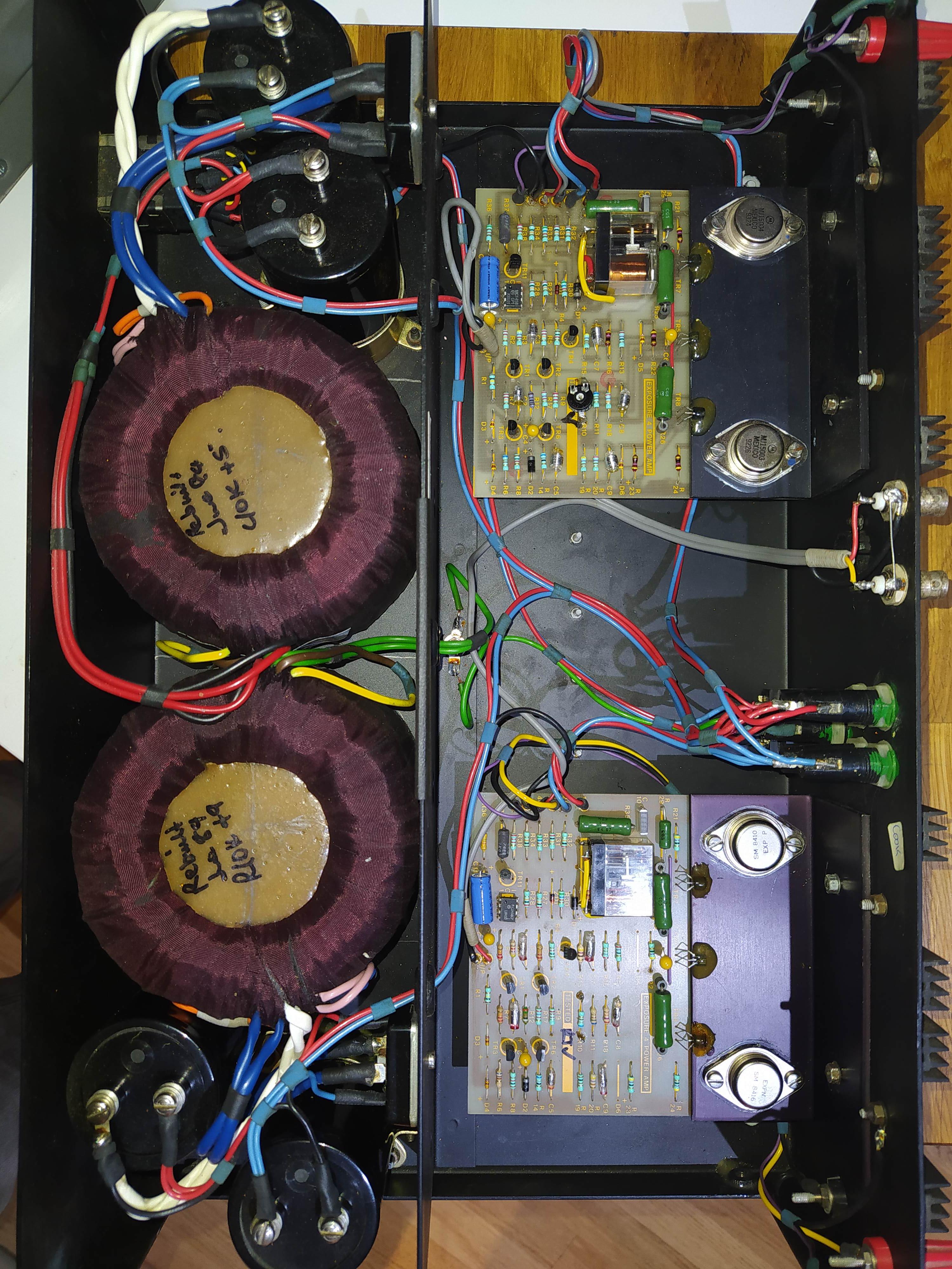
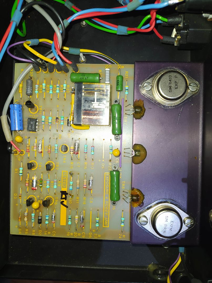
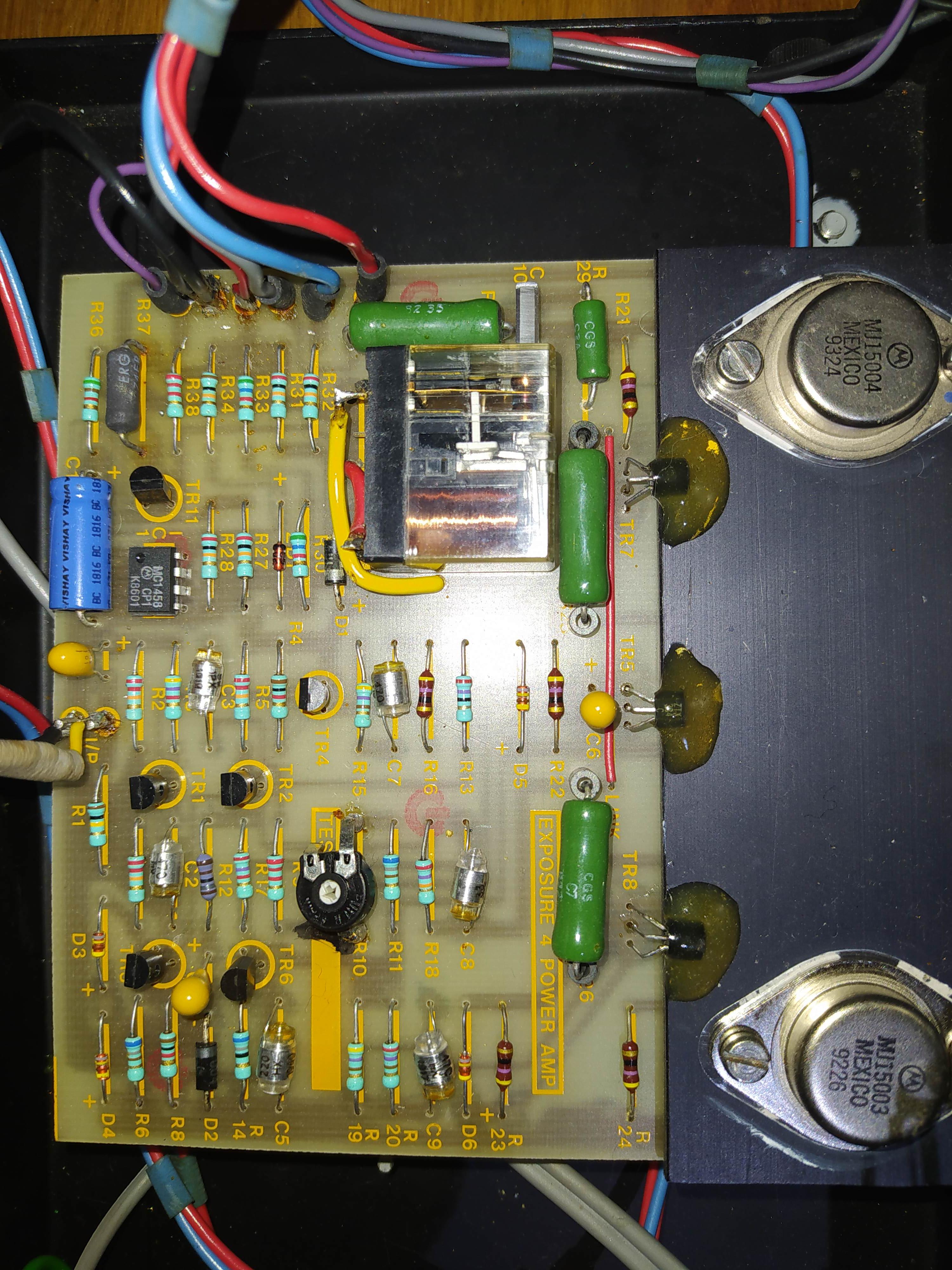
Picked up this huge beast...which apparently is blowing fuses.
Hoping to find any relevant Circuit diagrams that might be 'out there'.....please!!
Grateful for any information.....:)
 
I have an unregulated dual mono IV mk2 and the layout is rather simple. On mine, the blowing fuse problem was due to a shorted tantalum capacitor in the signal path. These old babies often have ground problems which is easy to cure with a bypass. Also, if it has relays and they are the original ones, they will need to be replaced. I couldn’t find the original for mine but I adapted some standard Omron that were easier to source. Here is the inside of mine:

 
Here are some pics.....looking similar to your amp Gervais!!
I can see some replacement power transistors...
itPKnxO.jpg

JRbX3tO.jpg

ihyMf1Y.jpg
 
Here are some pics.....looking similar to your amp Gervais!!
I can see some replacement power transistors...
itPKnxO.jpg

JRbX3tO.jpg

ihyMf1Y.jpg
Mine is from 1980 and yours looks like a 1984, very nice amp well worth the repair IMO.

Yours seems to be serviced lately as the light blue Vishay capacitors seem to be from 2018 and the large reservoir capacitors don’t look like the original ones so all good news.

Difficult to know if the relays are the original ones so are you able to see a date code on it ?
Anyway, I would change them as they tend to fail and cause many problems. Also, they seem to be side mounted instead of through holes so that will allow for many different options in terms of brand and model.

The tantalum capacitors look like they have been replaced as well so they may still be okay.

One of the R37 resistor seems to have traces of overheat so you may want to verify.

The little diodes like the D3 or D6 may also fail sometimes so maybe worth replacing them. I typically replace them all when I remove a board, these parts are very cheap anyway.

Another situation that sometimes happens with these amps is the thermal bridge between the support of the output transistors and the heat sinks loses its efficiency so repacking them with thermal paste is recommended.

Hope this helps.
 
Thanks Gervais....it all helps!! :)
Was wondering if the relays are not original...since they are mounted with flying leads, and also 'flat' to the PCB?
When replacing small diodes (without schematic)...how do you decide on component type/value....can it be seen on the diode body itself?
 
One small signal diode is much like another. It's often very hard to find any identifying marks but BAW 62 or 1n4148 will usually do.

It looks like a fairly competent repair and service has taken place. Is it just blowing fuses at power on occasionally?

If so and also the res caps are also oversized (quite likely to get ones physically big enough, the originals are only 10,000 uF and you're likely to need to go up to at least 15,000 or 22,000 to get the same size) then you've found the problem.

....good...have a shed load of 1N4148's..!
Transformers are marked as 'rebuild'...so who knows who did that work!
Haven't tried this yet....but seller described the sound of 'Galloping horses' from one channel before fuse went....not sure yet if this was the main fuse, or the channel fuse.
The res. caps are indeed 10,000 mfd (63v)....Norlin branded...and the seller suggested these weren't the originals??!
8csXzRD.jpg
 
Probably a factory rebuild in 1989 then. Those Lorlin caps are rebranded BHC and have a date code of week 13 1980 so are probably original to the amp.

The symptoms clearly indicate a fault so you're going to have to start pulling things apart to diagnose it , and the best place to start would be separating the amp board from the PS on the offending channel. Do you actually know which channel it is?

The fusing arrangements on the amp are not 100% clear from the pic. Doses it actually have five fuses? Looks like it may have one for mains, and one each for + and - rail to each amp board.

If the mains fuse has gone it's more likely to be a PSU fault than anything else

Yes....5 fuses....a total hotchpotch of values...none of 'em blown...so looks like the seller has 'helped' me there!!
I'll message him and see if he can remember which channel had played up!
 
Thanks Gervais....it all helps!! :)
Was wondering if the relays are not original...since they are mounted with flying leads, and also 'flat' to the PCB?
When replacing small diodes (without schematic)...how do you decide on component type/value....can it be seen on the diode body itself?
Yes, the relays seem to be replaced and like me, they couldn’t find the original ones so they fitted something that was available.
For the diodes, the value is written on it but you will need a magnifying glass to see it.
 
It’s a small through hole Omron and I had to drill some holes in the boards to fit them but it was very easy to do.
A few pins were not aligned with the circuit path so I did add some small wires to make the connection, again very easy to do.
I don’t remember the exact model of the Omron relay but I chose one with same specs as the original.
Same number of pin, normally open, right coil voltage and same contact voltage capacity or just slightly larger.
All of the specs of your actual relay are written on it as well so you don’t have to guess it. If not, there will be a part number and you just have to Google it to get all the details or post a few pictures here and we will let you know.
 
Unlikely to actually be the relay in that case. It's more likely either the relay driver circuit or there's a fault which causes the relay to open and as soon as it does re-sets and engages it again.
 
More hands up for blown fuses on mine ( Iv mk 2 unregistered ) lol. Fuses and new relays sorted by Tony as well. Have mine running with the rare dumpy, retro 3 pre amp, into a pair off transmission line DM 2 s for a lovely vintage moosical experience. Could start a blown fuse club maybe ?
 
More hands up for blown fuses on mine ( Iv mk 2 unregistered ) lol. Fuses and new relays sorted by Tony as well. Have mine running with the rare dumpy, retro 3 pre amp, into a pair off transmission line DM 2 s for a lovely vintage moosical experience. Could start a blown fuse club maybe ?
By unregistered, didn’t you mean unregulated ?
Anyway, this kit must be absolutely a real pleasure to listen to !
Makes many contemporary equivalent kits sound rather dry and bass shy against it I guess.


advertisement


Back
Top