advertisement


Exposure IV...any owners out there...some wiring/component anomalies!!

Tonewheelkev

...I can dream!!
I've included pics of both boards from my 'work in progress' Exposure IV power amp...perhaps any owners 'out there' might comment please??! :)

Essentially...the boards may well have undergone 'repair' (bodge?) over the years...resulting in some minor component 'differences'....all values same board to board (well as I've noticed so far that is)....but some components missing/added as extras??

Ideally, I'd like to get the boards back to 'stock'

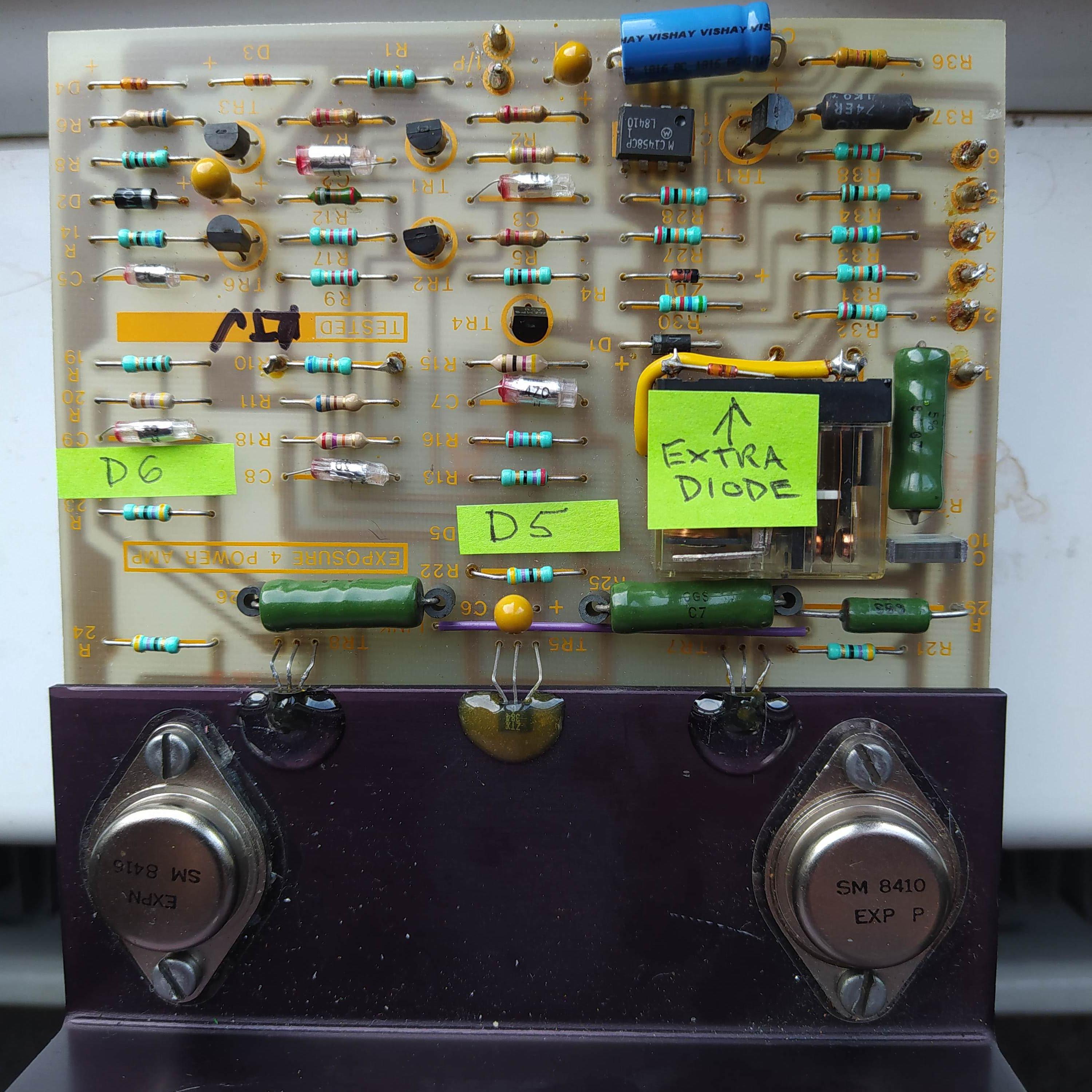
Here's Right channel.....haven't yet changed mustard Tants for electrolytics yet on this one.
As you can see...a couple of diodes not present....and an extra one to the relay coil.
Has...what I believe to be the 'original EXP transistors

MnBti69.jpg


....and....Left channel for good measure. Has preset (instead of fixed on Right channel)...for setting DC offset...I presume ???

svzMwe1.jpg


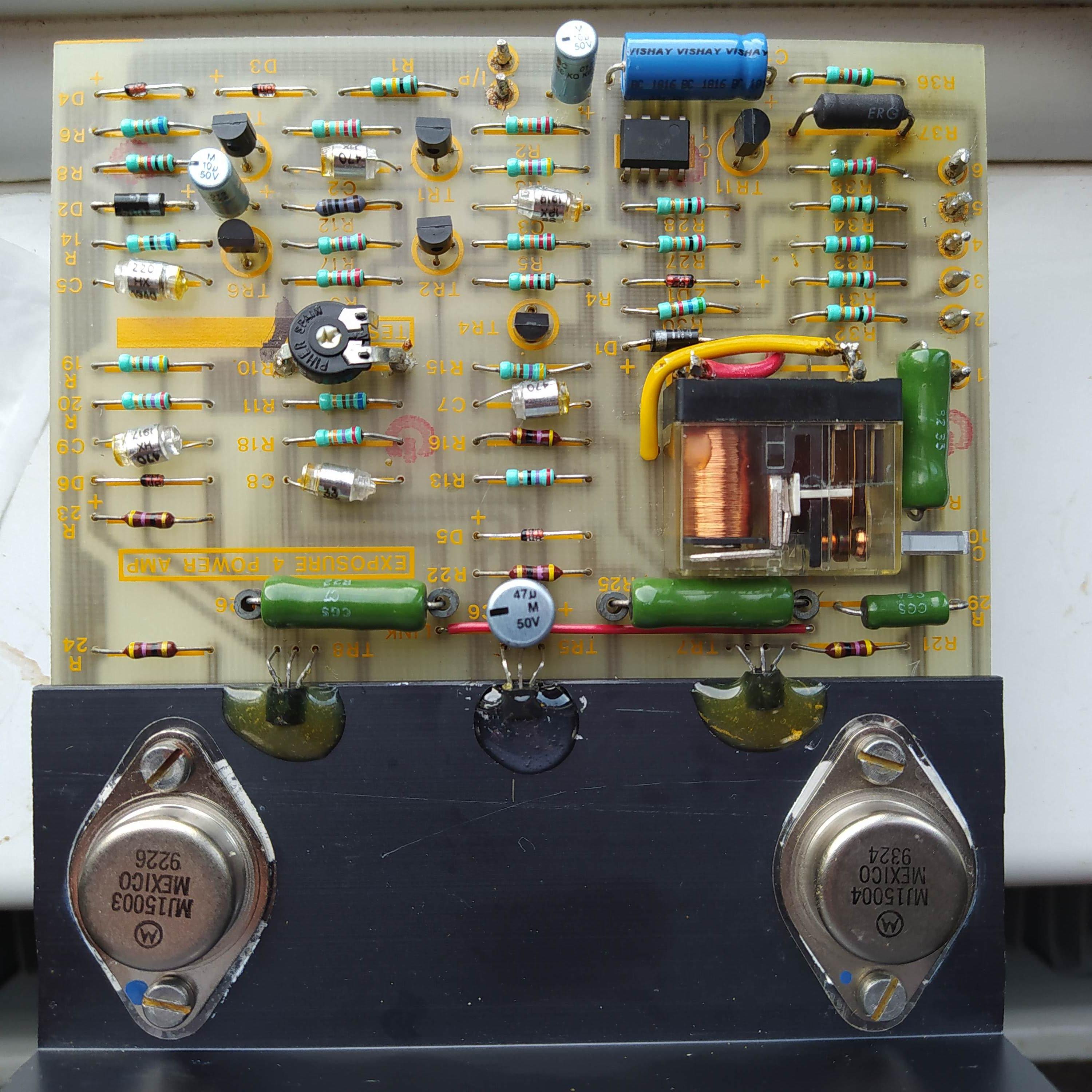
Will be acquiring at least one more pair of MJ15003/4....I imagine!

Perhaps it's the Aspergers in Me....but I want both channels to be the same:)
 
Both sides certainly should be the same!

which one doesn't work?

That preset is an outright bodge to try to get the quiescent current right. You'll see that the other board has a fixed resistor which has been soldered across two leads from the top. The correct way do this is initially start with a resistor slightly too high and then shunt it with reducing but order of magnitude larger values until you get an acceptable quiescent current. You then replace the whole thing with that combined value.
 
We all want the boards not to be dissimilar so we are all on the same page.

To me, it looks like a repair has been performed by someone that used whatever he had in hand..........

The small value caps were all tantalum back then so I would reinstall new ones with same value at first.

For the extra diode, it may replace the D5 missing so try to see if they follow the same path from one board to another. I saw people doing this kind of bypass when the path on the circuit board was peeling off.

The missing D6 remains a mystery for me.......

A good technician used to work on these or a similar Naim amplifier would be able to sort all this.
 
I'm also not too sure of the function of d5 and d6 but they look like they're across the collector resistors of the driver transistors, and are actually both doing the same job on opposite sides of the circuit. They may be normally reverse biased and performing a role similar to "catch diodes" on a main output stage (and therefore possibly optional).

I'm assuming the output stage must be a sziklai based on the small signal driver transistors.

(page 111 Horrowitz & Hill 3rd ed)

If I'm right a Naim technician may well have absolutely no idea what to do with it since it's a different design to Naim's.
 
OP needs to reverse engineer it and thereby get a circuit diagram for it. It would be folly to proceed any further without doing so.
 
Indeed - at least as far as figuring out exactly whether it's a darlington or sziklai type.

Probably second or third one of these options. Don't worry about the biasing arrangements, yours won't just be a stack of diodes.

https://sound-au.com/articles/dcp-f7.gif

The types of transistor and where the resistors go is what you need to figure out.

Bit of a bugger that the drivers are glued markings down!

Could also turn out to be a non unity gain output stage given that the driver to the right clearly seems to have a 47R collector and emitter resistor (assuming the base is the middle pin).
 
Right...couple of things first!
Currently working on a reverse engineered schematic...so on the way!
Had e-mail chat with Tony Brady himself today....transpires that the board was designed with MJ15003/4 in mind...but when the EXP transistors came along...then those boards "do not have D5 & 6 fitted",....and that the bias preset could be replaced by a fixed resistor.

So...got the non-working LH channel (with MJ15000's) re-installed after replacing tants...etc...and now see 10v at the relay coil (in faulty state this was at 36v)....DC offset started at 15mv...and then dropped to 3 'ish' mv after a minute or two!

Really pleased...no nasty smells or noises so far....might have cracked it.;)

Need to decide now on whether to bring both channels together as EXP or MJ15003/4 types...will need a couple of power transistors either way.
 
I've used Exposure twice before and there service has been brilliant and very good value for money.

Just thought i'd give the a plug and in case it helps.
 
It occurs that I never did update on this!!
Thanks to Jens in Germany...discovered that the anomalies I had noticed from board to board...were differences in the passive filter networks. (Resistor // Resistor+Capacitor(series)....hope that makes sense) Now they're both corrected, and consistent with the later spec IV boards. All now good...Dave, in York, put it through a scope and working as it should :)


advertisement


Back
Top