
You are using an out of date browser. It may not display this or other websites correctly.
You should upgrade or use an alternative browser.
You should upgrade or use an alternative browser.
DAC Kit - what else do I need? #2
- Thread starter Bemused
- Start date
- Status
- Not open for further replies.
James Evans
Bedroom Bodger
It's a squeeze in there isn't it! Where's the AC inlet going to be?
orangeart
KJF Audio Ltd.
I've had a bit more of a move around and found some more space, i'll be able to keep the STRs nearer where they need to be and still keep the flea and fleabite close to where they need to be. Leaving room for an AC inlet and some breathing room.
I've just been looking back through some old pictures on the thread and Tony's (Bemused) your multi gang flea looks the part. I've got Rich's reg boosters on the way but when your DAC is finally replaced by the shiny new Buffalo i'll definitely buy that from you if you want to part with it?
Stefan
I've just been looking back through some old pictures on the thread and Tony's (Bemused) your multi gang flea looks the part. I've got Rich's reg boosters on the way but when your DAC is finally replaced by the shiny new Buffalo i'll definitely buy that from you if you want to part with it?
Stefan
Whats going on over here then, ah sme picture to look at ")
Will have a look in detail tommorow Stefan as I hve been a little busy this lately mean while take a read afew pages back and see were SullfolkTony gained some improvement by adjusting his layout and wiring.
Will have a look in detail tommorow Stefan as I hve been a little busy this lately mean while take a read afew pages back and see were SullfolkTony gained some improvement by adjusting his layout and wiring.
Tony's (Bemused) your multi gang flea looks the part. I've got Rich's reg boosters on the way but when your DAC is finally replaced by the shiny new Buffalo i'll definitely buy that from you if you want to part with it?
Stefan
It is a rather expensve way of cranking up its performence but its informative and fun.
orangeart
KJF Audio Ltd.
take a read afew pages back and see were SullfolkTony gained some improvement by adjusting his layout and wiring.
Yeah, had a good look at that bit of the thread, very informative. Re-read the bit of the thread where you put the flea on standoffs above the fleabite as well. Amazing how much difference positioning makes isn't it.
I can't quite do what SF did because i am running op amps so there isn't the room for them there which is why i am planning on the position indicated.
i think i have dug up enough info to get the flea going, got a lot of taps open anyways! But i have a few more questions which would be god to get some answers to.
1. I've removed these components this evening in preparation for connecting in the STRs once i have built them up.

i think that's all ok? not sure what the 2 small film caps, resistors and leds do but until i know other wise i've left them in.
2. can anyone tell me what the other cap and reg to the left of this space is for? an also what the function of the circuit with the three transistors along by the relay is for?
3. LOBO you kindly said you would send me your reg boosters, i'm assuming you have them made up for the other 3 main regulator circuits and not all of the other smaller ones? I'll whip out the ones that need to come out in preparation.
4. Downloaded PSU D2 and got to grip with what does what but i must admit that i'm not really sure what i'm looking for, anyone got any links to getting my head around PSU design. I only really need to work out L or R for the other bits i've already got.
Cheers
Stefan
Yeah, had a good look at that bit of the thread, very informative. Re-read the bit of the thread where you put the flea on standoffs above the fleabite as well. Amazing how much difference positioning makes isn't it.
Yes dont put the flea above the flea bite, its not to clever, I thought it would be when I layed aout the board but it just did not work well.
i think that's all ok? not sure what the 2 small film caps, resistors and leds do but until i know other wise i've left them in.
They should be fine left in place, leds just indicate the supply is present, over time they become usefull for quick checks when the dac stops working.
2. can anyone tell me what the other cap and reg to the left of this space is for? an also what the function of the circuit with the three transistors along by the relay is for?
Stefan
No idea its not on my board,
Follow traces to see what it feeds.
4. Downloaded PSU D2 and got to grip with what does what but i must admit that i'm not really sure what i'm looking for, anyone got any links to getting my head around PSU design. I only really need to work out L or R for the other bits i've already got.
Cheers
Stefan
I am not aware of any links but in brief
Model the transformer correctly including its impeadence
Set the load to what your using, use the constant current feature.
Alter / extend the time time base to check when max voltage is achieved
Zoom into this flat area to look at the noise
The obejct is to reduce noise / ripple.
Kill most of the digital readouts just leave the load end as it just confuses.
Time playing with psuII is whats needed
orangeart
KJF Audio Ltd.
It's the zooming in i'm having trouble with, when i hit zoom in it moves in toward the middle of the chart not the part of the chart i need to look at. There doesn't seem anyway to scroll to the bit you need to look at. Am I missing something?
Stefan
Hi Stefan
Apologies for taking my time in posting the boosters, I have been away this week so will post early next week I promise. The boosters I have for you are 2 x 5V for the DAC and receiver etc and 2 x 3.3 V for the digital rails.
The extra reg and cap is a new addition to the board for 2011 i think, mine doesn't have those. I'm guessing that it is dedicated 12V for the relay as this used to be shared with the the op amp 12V section. I would leave it there for now, but remember it would need an unregulated DC supply.
One idea would be to bypass the relay section altogether and take the output straight from the LT1028's to the B4 input. You could also omit the B4 input caps seeing as you have output caps fitted, the DC from the op-amps is very small- does your power amp have input caps?
For the rectifier boards you can use something like 0.47R - 1R resistors.
I think you have a good layout, as long as the flea is happy your'e on to a winner. If you don't use the USB section you could strip the section or remove the supply and mount the flea above there maybe?
It's the zooming in i'm having trouble with, when i hit zoom in it moves in toward the middle of the chart not the part of the chart i need to look at. There doesn't seem anyway to scroll to the bit you need to look at. Am I missing something?
Stefan
Its not so much as zooming in on the image but making the data readouts (voltmeters) zoom in to the section you need.
I dont have psuII on the machine right now but you set simulation for say 120 secs to check were it flattens out.
Say this is around 2.1 secs
Then delay the simulation start point untill say 2.1 secs and only show perhaps five cycles 100mSecs
This way your digitl read outs, bottom left, most of which you switched off, will show voltage ripple after startup has occured.
The extra reg and cap is a new addition to the board for 2011 i think, mine doesn't have those. I'm guessing that it is dedicated 12V for the relay as this used to be shared with the the op amp 12V section. I would leave it there for now, but remember it would need an unregulated DC supply.
One idea would be to bypass the relay section altogether and take the output straight from the LT1028's to the B4 input. You could also omit the B4 input caps seeing as you have output caps fitted, the DC from the op-amps is very small- does your power amp have input caps?
For the rectifier boards you can use something like 0.47R - 1R resistors.
Good thinking on the extra reg Rich, bet thats what its for.
orangeart
KJF Audio Ltd.
Apologies for taking my time in posting the boosters, I have been away this week so will post early next week I promise. The boosters I have for you are 2 x 5V for the DAC and receiver etc and 2 x 3.3 V for the digital rails.
No worries it'll take me a while to get round to doing it all anyway, just whenever you're ready. I may need my hand holding as to which ones go where, do you think you could point me in the right direction of which res i can take out in preparation (presumably i'll have to take out the corresponding caps as well)
The extra reg and cap is a new addition to the board for 2011 i think, mine doesn't have those. I'm guessing that it is dedicated 12V for the relay as this used to be shared with the the op amp 12V section.
One idea would be to bypass the relay section altogether and take the output straight from the LT1028's to the B4 input.
I think that's correct, I haven't probed it yet but that looks like where it goes, I think i'm going to go with the signal routed from the op amp straight to the b4 via the pot idea so i probably don't need the relay and power for it anyway.
i can just extend the wire i currently use to bypass the buffer circuit to by pass the relay presumably?
You could also omit the B4 input caps seeing as you have output caps fitted, the DC from the op-amps is very small- does your power amp have input caps?
yes, does that mean i can omit the B4 output caps as well?
Thanks again for all the help guys
Stefan
Hi Stefan
Using your pic I have numbered the two 5V regs to be replaced by boosters:
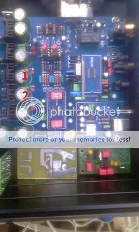
1 - high current, S/PDIF, up-sampler, toslink
2 - Low current, DAC chip
You will need to keep the large black filter caps but could maybe replace the green output caps for Panasonic FC, Nichicon KZ or such.
Yes just extend the dac signal wires straight to the B4 input. If you have input caps on the power amp then you could try removing the B4 output caps fitting 2K trimmers to R3, R103 on the B4 and trim out the DC completely. With the relay out of the equation you can remove the extra 12V reg and cap.
Or have output caps on the B4 and remove the power amp input caps. You might have more room in the B4 / dac to experiment with caps.
Another thought - it is best to have regulators as close as possible to the end circuit. You could mount the STR's in the space left by the 12V reg components, with the power transistors fixed to the DAC pcb with heatsinks or some metal plate as heatsink. Make sure you isolate the STR power transistors from each other.
Using your pic I have numbered the two 5V regs to be replaced by boosters:
1 - high current, S/PDIF, up-sampler, toslink
2 - Low current, DAC chip
You will need to keep the large black filter caps but could maybe replace the green output caps for Panasonic FC, Nichicon KZ or such.
Yes just extend the dac signal wires straight to the B4 input. If you have input caps on the power amp then you could try removing the B4 output caps fitting 2K trimmers to R3, R103 on the B4 and trim out the DC completely. With the relay out of the equation you can remove the extra 12V reg and cap.
Or have output caps on the B4 and remove the power amp input caps. You might have more room in the B4 / dac to experiment with caps.
Another thought - it is best to have regulators as close as possible to the end circuit. You could mount the STR's in the space left by the 12V reg components, with the power transistors fixed to the DAC pcb with heatsinks or some metal plate as heatsink. Make sure you isolate the STR power transistors from each other.
orangeart
KJF Audio Ltd.
right, i connected up the flea bite to the flea. A couple of things. I have a AC supply that gives about 250V! So i was expecting nearly 25V DC, I've got 32 hmmmm? Anyhow it's connected to the flea and the flea seems happy enough. Before I put the XO on the flea where do I test the voltage? and i'm presumably looking for 3.3 ish??
ta
ta
martin clark
pinko bodger
No probelm with the high raw supply.
You can test for output voltage at pin 7 of the opamp, or either end of L1, before installing the XO.
You can test for output voltage at pin 7 of the opamp, or either end of L1, before installing the XO.
- Status
- Not open for further replies.