advertisement


dŵr & Friends (how not to build a turntable).

Just for clarity: I suspect on an absolutely level playing field, e.g. same motor, same speed, same degree of step-down etc a belt drive is the superior system. It just has to be because it is inherently quieter. The big ‘but’ is that it isn’t a level playing field and the classic idlers from EMT, Garrard, Lenco and Thorens have vastly more torque than a belt-drive deck can imagine, so really we are comparing entirely different things.
 
I suspect you (and for that matter VPI) may be missing a key logic point of the TD-124 drive system, and that is the sheer speed and torque it generates.

Could be - I meant in no way to infer that the rim drive presented here was a replica of the TD-124's, but merely to show that as opposed to other idlers, this rim drive uses a belt to transfer power from the motor to the friction wheel, as opposed to driving the idler directly - as a similarity to the TD-124 drive in that manner.

My approach does not rely on an eddy brake (mass does help with smoothing a bit), but it does rely on a (1) high torque (~0.1 Nm - 4x more than the Maxon DCX popular with high end manufacturers, and 6x more than the 300rpm Hurst that VPI uses), (2) fast spinning motor. As a matter of fact, in my implementation, it spins at ~710 rpm for 33.(3) and ~960 rpm for 45.0.
 
My approach does not rely on an eddy brake (mass does help with smoothing a bit), but it does rely on a (1) high torque (~0.1 Nm - 4x more than the Maxon DCX popular with high end manufacturers, and 6x more than the 300rpm Hurst that VPI uses), (2) fast spinning motor. As a matter of fact, in my implementation, it spins at ~710 rpm for 33.(3) and ~960 rpm for 45.0.

It is a fascinating subject. I must admit I’ve never understood the logic behind the VPI rim-drive deck at all. To my eyes it’s a nice solid belt-drive deck with an idler for no apparent reason. It just looks to have the ‘gearing’ in entirely the wrong direction, i.e. it steps-up and loses torque, rather than stepping down and gaining it, so really all they look to be doing is adding a mechanism to generate rumble for no apparent reason! If someone could explain the logic behind it I’m all ears! What does it bring over the belt-drive version?
 
Either way, this is a great thread, not only because of @InSides wonderful photographs and keen exploration his subject matter, but also because we're discussing rim/idler drives! Worth a separate thread I guess, because I'd really like to know how much more I can extract from the 401!
 
VPI must have their reasons, although they have shown repeatedly they are not at all keen at explaining.

To my eyes - they seem to be adding technologies to their line up as they become FOTM, or to fix previous inadequacies. Shame really as they seem to have the resources to engineer things properly from the get-go.
 
Given the dogshit vpi use as an AC motor I'm inclined to not regard their engineering logic too highly.

Tony, is the td124 motor shaded pole like the Lenco g99 part. If so cogging should be none existent.

A high rotational mass in the platter helps the belt to mitigate motor caused speed variance at the cost of bearing noise. An eddy brake increases the load the motor sees without increasing platter mass and thus bearing load. Adding 'drag' to the motor with an eddy brake helps compress the magnetic field in an ac sync motor and mitigates cogging. You can do the same with higher viscosity bearing oil.

Both approaches dwarf changes in stylus drag in terms of force and hence linearise speed.
 
May I ask a question regarding your bearing design.
Is the 8mm ceramic ball a press fit into the shaft or free to rotate within the tolerance of the ball versus the 8mm dia * 4mm deep bore in the shaft end.
 
May I ask a question regarding your bearing design.

Most certainly!

Is the 8mm ceramic ball a press fit into the shaft or free to rotate within the tolerance of the ball versus the 8mm dia * 4mm deep bore in the shaft end.

It is not press fit. Theoretically, it is free to rotate, but the tolerance is such that the ball is held in place with a few drops of very thin machine oil in the bore at the shaft end.

I considered permanently fixing the ball, but wanted to have the flexibility to easily replace it if (or when) it gets worn, as I had every intention to experiment with thrust surfaces. That intention has now melted away in the time spent actually listening to music, and the Vespel option is very good as a thrust surface in this application.

Additionally, early experiments with a fixed ball tended to be rather more noisy, but that may have been due to the fact I did not really spend any time and effort to properly (permanently) fix the actual ball. Not to mention that (1) the level of surface finish and sphericity of the ball makes it difficult for any adhesive to do its job, and (2) any press work on a precision shaft may very likely mess up the shaft tolerance.
 
Im asking because Im about to fit a 5mm ball on the end of the shaft in one of my technics bearings.( heavily modified from the original technics design) Technics machine the semisphere on the shaft end, it wears and new stock is no longer available.
I agree a firm press fit might not be ideal.
I want to avoid two bearing surfaces and any "x" "y" movement of the ball. My thinking at the moment is to use a lathe centre drill to make the bore on the shaft end. This will give me a bearing stop formed from an inclined angle of 60 degrees and keep the bearing centralised on the shaft Z axis minimising any XY movement and make the bedding point of the ball on the industrial plastic bearing support more accurate. Im about to order some parts to do this
Have you tried using silicon oil in the bearing shaft and support. CST 50 to CST 100 works well for me.
 
Silicon oil isnt really suitable for a technics like, all metal bearing, doesnt have the required antiwear. Fine in composite sleeves bearings, or maglevved linns. Ime.
 
Using a center drill on the lathe seems like a good idea to ensure that the ball is centered.

As for silicon oil, I cannot say I have tried. I use a very low viscosity oil, typically used for high speed knitting machines.
 
Silicon oil isnt really suitable for a technics like, all metal bearing, doesnt have the required antiwear. Fine in composite sleeves bearings, or maglevved linns. Ime.

Thanks for your feedback.
Ive been using CST50 for over two years on two decks with no issues. My modded bearings are running completely in oil unlike the std technics 1200. Ill delve deeper and see If I can find out more for my own education.
We dont of course know the precise type of "Bronze" used by technics.
 
Well I have to say that your work is stunning. Leaves me both dumb-struck and awestruck. Unfortunately it also makes my efforts look like those of an idiot with a mallet!
On the subject of "free" and "captured" (interference fit) ball element thrust bearings, I wonder if increased noise with the captured ball is due to the press-fitting operation. With a free ball resting against an accurately machined conical seat there should be good alignment of the contact point of the ball and thrust pad with the bearing axis, providing of course that the thrust pad is flat and square to the bearing axis. With a press-fit I suspect that there can be uneven "give" in the walls of the hole into which the ball is pressed yielding slight axial misalignment. There is also the possibility of putting a tiny flat (or other localised deformation) onto the surface of a steel ball
 
Have completed the prototype of my technics bearing mod with a 5mm ceramic ball on the shaft end fitted into a 60 degree centre bored hole. Oil holds the ball in place ( I only lost two when the shaft was out ! ) The contact area onto the bearing support is reduced relative to the technics shaft end profile. My platter is modified from the original technics to get rid of the inbuilt resonance but the weight is almost identical. Lightweigh compared to most belt drive TTs.
My deck is running now and the indications are that there is slightly more detail and better channel separation. Ill do some measurements when the prototype has run in for a week or so and check the bearing support. I made my new shaft from silver steel and bored out the technics bearing to take a larger diameter. Hardened the silver steel. If successfull ill look at getting a bearing and shaft produced to a higher tolerance. Technics complicate the shaft with their taper fit into the platter and the critical platter height for motor clearance
I have also taken on board the feedback from sq225917 re anti wear properties of silicon oils. I found low viscosity oils from Miller Oils in Yorkshire which I am now using.
 
That is excellent! :)

On the topic of tapered shafts, they do require more precise manufacturing, but the taper is very beneficial methinks when it comes to proper fit and positioning. Assuming the taper angles are correct, concentricity is a given. Kuzma used to use tapered platter supports for their subplatter-driven turntables - works very good for them as well.
 
An interesting (although not at all unexpected) update today.

But first, a bit of history. When I completed the flywheel for the rim drive approach, I knew there would have to be some compromises regarding the contact surfaces and pulley + flywheel + platter interfaces. I had originally ordered, from a local supplier, a number of different sized Buna-N (NBR) "precision" o-rings with a 3mm diameter cross section.

I had intended to use one type of o-ring for the rim wheel surface, and another as a belt between the pulley and the flywheel. It turned out that the o-ring was nowhere near compliant enough to be used as a belt, so I dropped that idea. The only other viable approach, in the middle of a lockdown, was to sacrifice one of my very compliant 2mm square section belts and glue up an appropriate (smaller) belt. I took what I felt was great care, doing 45 degree cuts and gluing up while clamped in a POM-lined vise, but it seems I have much to learn about making an invisible splice.

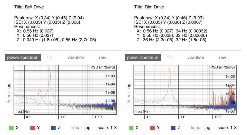
The belt did work (and still does) but the spliced section caused some vibrational artifacts when passing over the pulley and at different parts of the flywheel. This, in conjunction with the imperfect surface of the "precision" o-ring that comprises the rim-to-platter interface resulted with some visible peaks during vibrational measurement on the Z axis, as visible on this graphic included with a previous post (right section).

0XEE7D5.jpg


Knowing I had to solve both these issues eventually (belt and rim interface), ordered a number of smaller belts from Thakker. They did not have a 2mm cross-section, so went with 1.3mm cross-section in a size near to my requirements (I have some flexibility in positioning due to the design). They are very compliant and have a nice grippy surface.

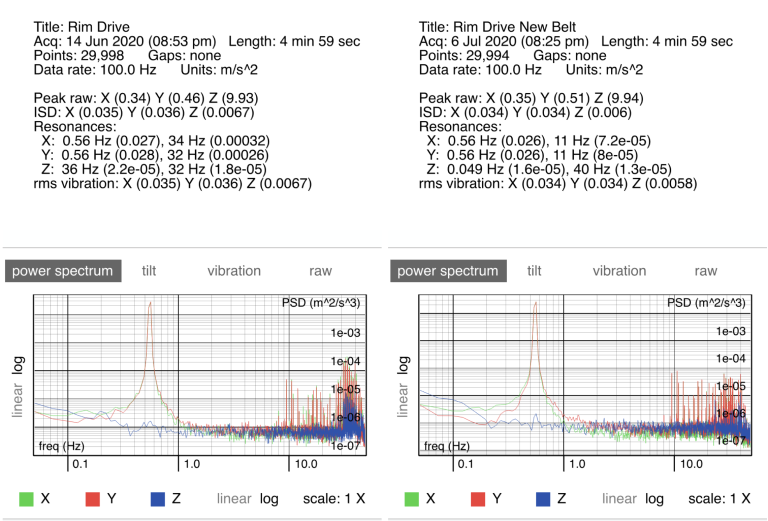
Well, I hate to be Captain Obvious, but the importance of a properly made belt (with no tactile splices!) should be clear. Here is a new measurement comparing rim drives, with the old (spliced) and new (Thakker) belt.

qTE3VLl.png


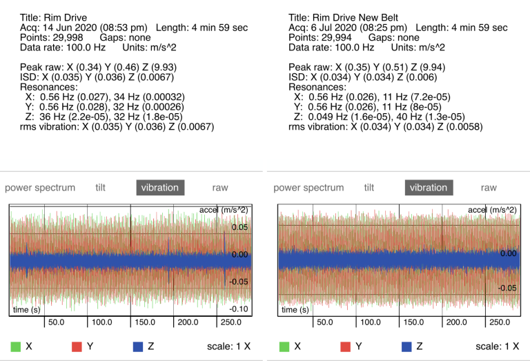
And here is an overview of the vibration graphs:

GgJkJjo.png


The new belt behaves much nicer, with cleaner start up routines, improved braking time, and no visible vibrational artifacts.

Now, to figure out how to get a o-ring that is actually precise. Thinking of white EPDM, but need to source it from abroad, so will take some time.
 
Last edited:
I've not done much messing about with belts, but a flat section has always been more stable and quieter than an o ring, I assume its because the ate ground post moulding and usually lower durometer.
 
May I ask for a pointer as to the software you use to measure TT performance ?
I currently use Arta via my PC or the spectrum analyser on my Pico Scope with appropriate test records.
I have now made two new bearings for my (2) technics. Shaft dia 10% larger and bearing length 12% longer than standard and running in oil.
Thank you for your enthusiasm making me delve deeper.


advertisement


Back
Top