
You are using an out of date browser. It may not display this or other websites correctly.
You should upgrade or use an alternative browser.
You should upgrade or use an alternative browser.
dŵr & Friends (how not to build a turntable).
- Thread starter InSides
- Start date
InSides
dŵr
Nice polars, zero signs of cogging
These motors are really good performers. Proper ball racing bearings top and bottom, with very good radial tolerance, which allows me to pull off some crazy ideas. I would not mate an idler directly to the spindle (and I didn't) but anything else seems to be game.
Even if the bearings get sloppy at some point (which is less likely since they are not sleeves) both can easily be replaced.
InSides
dŵr
This Is extraordinary work, you should be very proud. How are you able to produce these bespoke components - do you have CNC and milling machines?
Only the wooden plinths are a product of a CNC mill, just because it was way cheaper than doing it by hand. Did require a lot of hand sanding though to reach that level of finish - and only a few coats of oil.
Everything else is on a manual lathe. I am lucky that I became close friends with an extraordinary machinist with whom I have managed to, over the years, achieve a common understanding. What once needed a 5-page technical drawing for a single component now boils down to 4-5 sentences over the phone and he knows exactly what is expected.
Which is why, even if I ever get the desire to go that way, it will never be commercially viable, this level.
")
InSides
dŵr
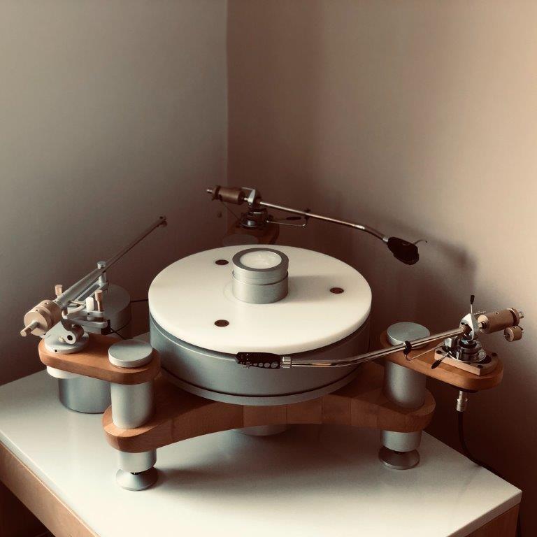
Step #5. Tonearm.
The final step in this cycle is a new tonearm. Specifically, a conversion of a SME 3009 to a 3012. And with that, I am coming back full circle of my current audiophile journey, given the fact when I first set up a turntable in my home, classic SME tonearms were impossibly ugly to me, and I did not even want to think about SPUs.
My thanks to the years I've shoved under my belt, so that I could naturally see the light.
Introduction
Before we get to the how, let us clear the air about the why.
Why 12" effective length is easy to answer. For a properly engineered tonearm, longer means lower tracking error, but only if one can accomodate said tonearm length on a standard sized turntable.
Why SME 3012 is even easier to answer. I am in love with SPUs.
Why a conversion of an existing 3009 to a 3012? Because, (1) even if I bought a 3012, I would probably go through the same modifications as detailed here, and the items I retain are identical with the 3009, and (2) 3009 is much cheaper (even with current price hikes) than a 3012, even including the price for the tonearm tube. Now, even as the newer donor I bought is close to 5x more expensive than the other one I already had and bought 10 years ago, I can still consider this approach to be cost effective.
Work
The process I undertook involves the following steps:
1. Tonearm disassembly. Relatively simple, and the service manuals available on the VE are quite useful. An important note for people in countries which adhere to the metric system, hex keys in imperial sizes are needed but may be difficult to find (I had to order mine from abroad). In addition to these hex keys (3/32, 7/64 and 1/8), a few small screwdrivers and needle nose pliers. In my two tonearms, SME had also used metric sized fasteners, so there is that too.
Now, almost all of the SME 3009 tonearms I've seen and handled (not too many though) have been in very good shape, so that I had never needed to force parts apart. I did not take detailed pictures of the process, but the order I took was this:
Perhaps this is true. I believe I've established by now I like the trust, but verify approach.
No matter how high quality, these are 50+ years old open bearings. I understand things were being better built back in the day, but come on. Specifically - 9mm x 17mm x 4mm open bearings, forced to act as thrust bearings, which is a bit of an unnatural position for them - although the weight loads are quite tolerable.
So let us see how good they still are. I built a wooden frame with a POM axle to allow for the bearing to roll freely, positioned a smart phone's microphone at a 10cm distance, then excited the bearings manually for three separate rotations and recorded the sound. The recording was done in a quiet room, but still cleared of backround noise using a very gentle noise reduction algorithm courtesy of Audacity.
As actions speak louder than words, here (*) is what the OEM bearing sounds like:
https://soundcloud.com/marjan-stojnev/bearing-chatter-oem-sme-3009
What about a new bearing?
https://soundcloud.com/marjan-stojnev/bearing-chatter-skf-hybrid
Quite some difference, don't you think?
(*) PFM's XenForo would not let me embed SoundCloud clips - hence the links.
The new bearings (yes I went with new - wouldn't you after hearing that grating noise) are made by SKF, and are labeled as ceramic hybrid bearings, type 618/9, dimensions 9mm x 17mm x 4mm. These are open bearings, with a stainless steel housing, and Si3N4 ceramic balls. This type of hybrid bearings are not readily available commercially. Luckily, the local SKF distributor had ordered a large batch with a custom order to accomodate a local industry which uses them regularly.
Here is a view of a dismantled tonearm pillar:
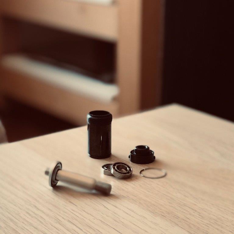
Assembly is quite simple - save for taking core of proper preload of the pillar bearings - as done by tightening the bearing cap cover. Preload set for the minimum amount of stiction possible.
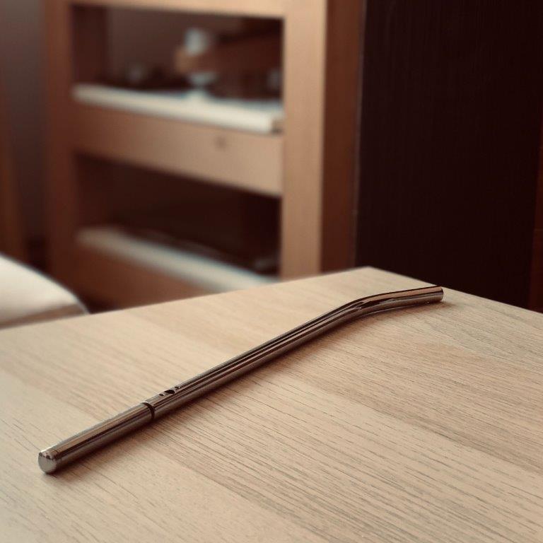
3. Changing the tonearm tube and the knife edge bearings. The knife edge bearing is machined out of bronze, ordered via eBay. Made no sense to machine it locally for the price requested. Quality is excellent. The tonearm tube is an OEM 3012, but the rear stub is now mated to the tonearm tube via a semi-rigid mount machined out of polyoxymethylene (POM) to try and avoid the counterweight sagging issue.
This is what the tonearm tube looks like prior to the knife edge being mounted:
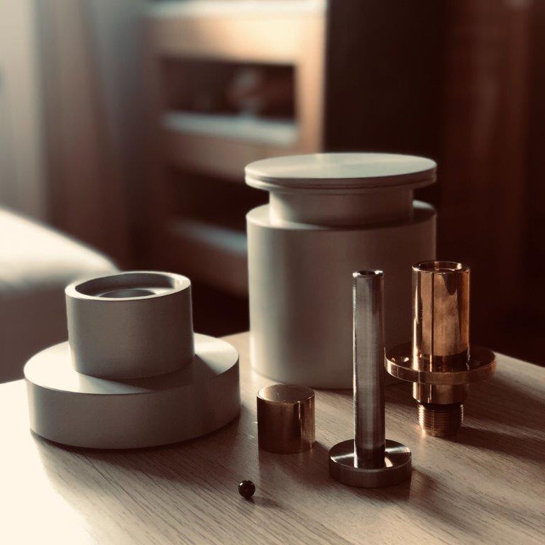
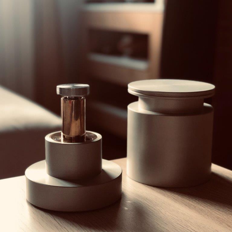
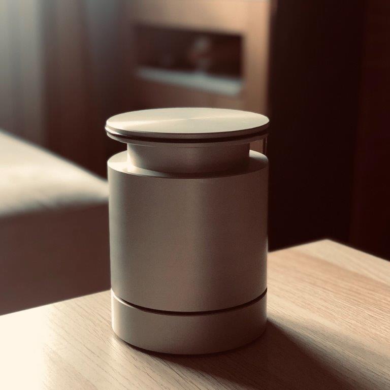
4. Manufacture and installation of a new counterweight set. A full set, machined out of C932 bronze. The number of counterweights for a full set is not trivial, and, keeping in mind the material choice, I had to do slight modifications to external dimensions to keep the final mass closest to OEM.
In the hope that someone finds this useful, here is a technical drawing of the counterweight set:

Like with the bearing, the weights are lightly sandblasted using glass media, at a 50µm granulation, then TiN plated via PVD.
As the proof is in the pudding, this is what they looked like freshly back from finishing:
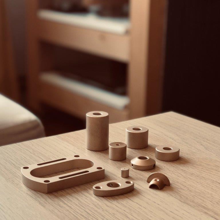
The photo shows two more components not mentioned before. The first component is a 10mm high bronze spacer, courtesy of the same eBay seller as the knife edge. I had quite the noticable improvement using this to mount the previous SME (and eliminate the rubber mushrooms), so it was a no brainer here.
Another component is an oval connector mount for the tonearm cable. As with the earlier conversion, I decided to go straight to a 5-pin DIN connector to mate to a readily available tonearm cable. The connector used is a PTFE body with goldplated brass pins (1877-phono). I did not provide for the dimensions of this component as it needs to be mated to the screening can (and there are different dimensions of screening cans) - but if anyone needs further details about how to make one, I will be happy to oblige.
5. Rewiring. After assembly, the tonearm tube is damped using untreated sheep wool, and wired using silk isolated copper litz wire. The SME headshell connector has been thoroughly cleand, along with the SME headshell, and the headshell wires have been replaced by Ortofon's standard set. The SME headshell never grew on me, but as the plans for a SPU Royal were kicked royally in the nether regions by "the great crisis of 2020", it serves to protect the SME connector from dust.
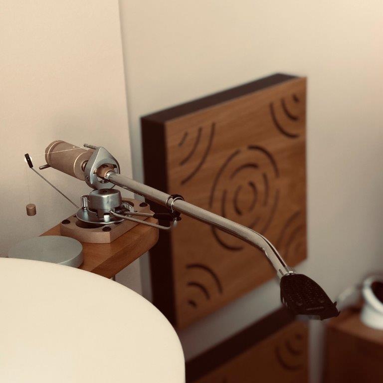
Finally, a view of the mounted tonearm:
And a happy family photo:
Results
Still amazes me that I knew what to expect, and it still put a smile on my face.
Luckily, (1) SME 3009 prices are still on the rise, and (2) there are no more free tonearm mounts on the turntable, or I would be tempted to do another.
The final step in this cycle is a new tonearm. Specifically, a conversion of a SME 3009 to a 3012. And with that, I am coming back full circle of my current audiophile journey, given the fact when I first set up a turntable in my home, classic SME tonearms were impossibly ugly to me, and I did not even want to think about SPUs.
My thanks to the years I've shoved under my belt, so that I could naturally see the light.
Introduction
Before we get to the how, let us clear the air about the why.
Why 12" effective length is easy to answer. For a properly engineered tonearm, longer means lower tracking error, but only if one can accomodate said tonearm length on a standard sized turntable.
Why SME 3012 is even easier to answer. I am in love with SPUs.
Why a conversion of an existing 3009 to a 3012? Because, (1) even if I bought a 3012, I would probably go through the same modifications as detailed here, and the items I retain are identical with the 3009, and (2) 3009 is much cheaper (even with current price hikes) than a 3012, even including the price for the tonearm tube. Now, even as the newer donor I bought is close to 5x more expensive than the other one I already had and bought 10 years ago, I can still consider this approach to be cost effective.
Work
The process I undertook involves the following steps:
- Tonearm disassembly;
- Changing pillar bearings;
- Changing the tonearm tube and the knife edge bearings;
- Manufacture and installation of a new counterweight set; and,
- Rewiring.
1. Tonearm disassembly. Relatively simple, and the service manuals available on the VE are quite useful. An important note for people in countries which adhere to the metric system, hex keys in imperial sizes are needed but may be difficult to find (I had to order mine from abroad). In addition to these hex keys (3/32, 7/64 and 1/8), a few small screwdrivers and needle nose pliers. In my two tonearms, SME had also used metric sized fasteners, so there is that too.
Now, almost all of the SME 3009 tonearms I've seen and handled (not too many though) have been in very good shape, so that I had never needed to force parts apart. I did not take detailed pictures of the process, but the order I took was this:
- Remove movable parts (counterweights, skating force compensation, cable connector mounts);
- Unmount the tonearm yoke, remove the wiring connectors and the spider at the end of the tube;
- Dismantle the pillar (by pulling it from the top!); and,
- Dismantle the pillar bearings.
Perhaps this is true. I believe I've established by now I like the trust, but verify approach.
No matter how high quality, these are 50+ years old open bearings. I understand things were being better built back in the day, but come on.
Specifically - 9mm x 17mm x 4mm open bearings, forced to act as thrust bearings, which is a bit of an unnatural position for them - although the weight loads are quite tolerable.So let us see how good they still are. I built a wooden frame with a POM axle to allow for the bearing to roll freely, positioned a smart phone's microphone at a 10cm distance, then excited the bearings manually for three separate rotations and recorded the sound. The recording was done in a quiet room, but still cleared of backround noise using a very gentle noise reduction algorithm courtesy of Audacity.
As actions speak louder than words, here (*) is what the OEM bearing sounds like:
https://soundcloud.com/marjan-stojnev/bearing-chatter-oem-sme-3009
What about a new bearing?
https://soundcloud.com/marjan-stojnev/bearing-chatter-skf-hybrid
Quite some difference, don't you think?
(*) PFM's XenForo would not let me embed SoundCloud clips - hence the links.
The new bearings (yes I went with new - wouldn't you after hearing that grating noise) are made by SKF, and are labeled as ceramic hybrid bearings, type 618/9, dimensions 9mm x 17mm x 4mm. These are open bearings, with a stainless steel housing, and Si3N4 ceramic balls. This type of hybrid bearings are not readily available commercially. Luckily, the local SKF distributor had ordered a large batch with a custom order to accomodate a local industry which uses them regularly.
Here is a view of a dismantled tonearm pillar:
Assembly is quite simple - save for taking core of proper preload of the pillar bearings - as done by tightening the bearing cap cover. Preload set for the minimum amount of stiction possible.
3. Changing the tonearm tube and the knife edge bearings. The knife edge bearing is machined out of bronze, ordered via eBay. Made no sense to machine it locally for the price requested. Quality is excellent. The tonearm tube is an OEM 3012, but the rear stub is now mated to the tonearm tube via a semi-rigid mount machined out of polyoxymethylene (POM) to try and avoid the counterweight sagging issue.
This is what the tonearm tube looks like prior to the knife edge being mounted:
4. Manufacture and installation of a new counterweight set. A full set, machined out of C932 bronze. The number of counterweights for a full set is not trivial, and, keeping in mind the material choice, I had to do slight modifications to external dimensions to keep the final mass closest to OEM.
In the hope that someone finds this useful, here is a technical drawing of the counterweight set:
Like with the bearing, the weights are lightly sandblasted using glass media, at a 50µm granulation, then TiN plated via PVD.
As the proof is in the pudding, this is what they looked like freshly back from finishing:
The photo shows two more components not mentioned before. The first component is a 10mm high bronze spacer, courtesy of the same eBay seller as the knife edge. I had quite the noticable improvement using this to mount the previous SME (and eliminate the rubber mushrooms), so it was a no brainer here.
Another component is an oval connector mount for the tonearm cable. As with the earlier conversion, I decided to go straight to a 5-pin DIN connector to mate to a readily available tonearm cable. The connector used is a PTFE body with goldplated brass pins (1877-phono). I did not provide for the dimensions of this component as it needs to be mated to the screening can (and there are different dimensions of screening cans) - but if anyone needs further details about how to make one, I will be happy to oblige.
5. Rewiring. After assembly, the tonearm tube is damped using untreated sheep wool, and wired using silk isolated copper litz wire. The SME headshell connector has been thoroughly cleand, along with the SME headshell, and the headshell wires have been replaced by Ortofon's standard set. The SME headshell never grew on me, but as the plans for a SPU Royal were kicked royally in the nether regions by "the great crisis of 2020", it serves to protect the SME connector from dust.
Finally, a view of the mounted tonearm:
And a happy family photo:
Results
Still amazes me that I knew what to expect, and it still put a smile on my face.
Luckily, (1) SME 3009 prices are still on the rise, and (2) there are no more free tonearm mounts on the turntable, or I would be tempted to do another.
InSides
dŵr
Perhaps a parallel tracker... There you go, the challenge.
Hah! The original design anticipated a parallel tracker which mounts on two of the tonearm mounts in a bridge like fashion. I may still do it.
But first things first, the rim drive.
InSides
dŵr
Weary travellers, we hare reached the current point in time, and the completion of the rim drive.
Introduction
Perhaps the biggest appeal to analogue reproduction to me is quite the established dichotomy between the nature of the reproductive apparatuses and the material itself. A thing which is arguably archaic in the digital age, such as vinyl reproduction, can pretty much always be improved and adapted via investments to new appreaches, especially modern technologies and material combinations.
And it is not as if no desires for disruptions in the vinyl space had ever come to pass (see ELP). But the thing that really fascinated me (and still does!) is the clinging to somewhat archaic and apparently worse methods of reproduction such as rim drives. Users who have had experiences with rim drive seem to swear at the rhythmic excellence of said approachs, and the prices of the various idler equipped turntables seem to be on a steady upward trend.
How would I ever be able to live with myself if I didn't check?
Execution
Little imagination is needed to understand why idler drives are not more popular with typical turntable manufacturers, and why most designers (yours truly included - would humbly add himself to that group) stick to a belt drive:
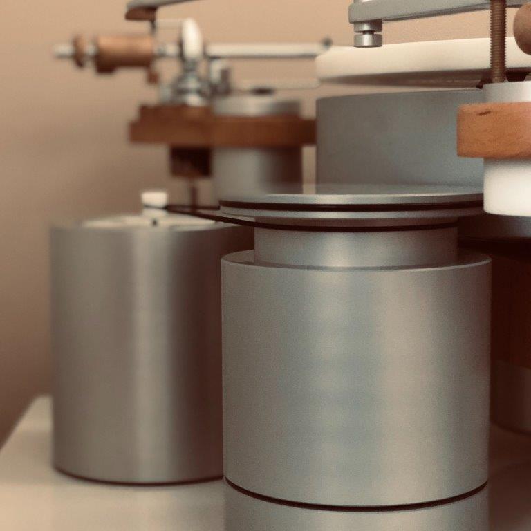
Slight twist in all this is that bolting an idler wheel to the motor spindle would simply not do. Having had a proper bearing already, I would go ahead and do a proper flywheel and friction wheel (idler) combination. I've already used the flywheel effect with the turntable platter, and wanted to see if I had already reached the "too much of a good thing" point in the build.
When in pieces, nothing spectacular about the flywheel assembly.
Earlier readers of this thread may recognize dŵr's old bearing. Why waste a good thing, right? Machined out of C932 bronze, hardened steel spindle, Vespel SP-21 thrust plate and a 8mm diameter ceramic ball (Si3N4, G5). Base of the flywheel assembly machined out of aluminium (6082), the material of choice for the flywheel itself. External diameter at exactly 120 milimeters, which brings us down to ~2.6kg of movable mass for the flywheel to take advantage of increased moment of inertia.
Putting the bearing together with the base makes for a more compact structure.
Which only leaves topping off with the flywheen and installing the butyl rubber precision o-ring.
Finally moved to its proper working position.
Principle
I have been lucky that with sheer mass and brute force could avoid designing and implementing a precise mechanical assembly to exert continued pressure between the idler and the platter. The flywheel (with the integrated rim wheel / idler) is driven by a square section belt, similar to the Thorens TD-124 approach, allowing for an additional isolation level. Speed regulation and monitoring courtesy of the algorithm described earlier in this thread.
Once a new pulley was in place, switched the order of motor phase supplies (for a direction swap) and let the motor run for some time to account for the changes in the drive ratio.
Measurements
I could go on for days writing on the topic with varied success, but as proof is in the pudding, we should check what a few measurements show.
Speed stability. In a similar vain to the measurements described earlier when swapping motor pods, I collected data from 160 individual data points and tried to establish the variance of speed stability. Note that all measurements take in account belt and rim drives, but (!) in both cases, the flywheel was used.
To start with, W&F for the measurement cycle:
Belt.
Average W&F: 0.0062%
Worst W&F: 0.0121%
Median W&F: 0.0065%
According to the NAB specification, worst allowable W&F value for reproduction purposes is 0.1%. Well, even in the worst case scenario, this turntable, when belt driven, exceeds that specification by ~8х (8 times), and at average, exceeds it by ~16х (16 times).
Rim.
Average W&F: 0.0081%
Worst W&F: 0.0164%
Median W&F: 0.0079%
Somewhat worse numbers. By how much though? Again, according to the NAB specification, worst allowable W&F value for reproduction purposes is 0.1%. This turntable, when rim driven, in the worst case scenario, exceeds that specification by ~6х (6 times), and at average, exceeds it by ~12х (12 times).
When plotted using a standard radar / polar diagram, the following is shown.
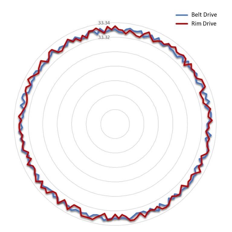
Rim drive clearly fluctuates more, but in no case was the measured speed below 33.32 rpm or above 33.34 rpm, bringing up the total variance to ± 0.02% in the worst case scenario (which still, even at that point, exactly 5 times betters the declared NAB specification). (*)
(*) OK, I promise to stop mentioning NAB further.
Vibrational characteristics. As with previous approaches, I utilized an iOS application which reads the values off of internal sensors, and compared the effects of the belt drive and the directly coupled rim drive, precicely at the level of the reproductive surface of the turntable.
The result of using a flywheel and a two belts (pulley to flywheel, flywheen to platter) is easily the best vibrational state this turntable has ever seen.
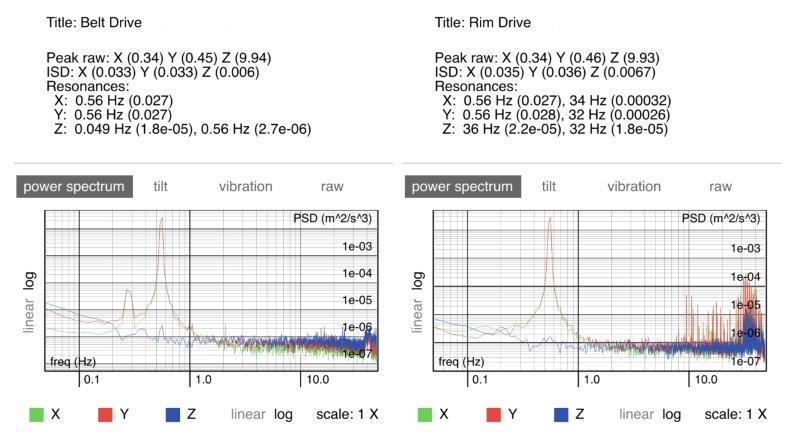
At both graphs, the X and Y axes show the standard resonant frequency peak at 0.56Hz, which relates to the 33.(3) rpm rotation of the platter. Additionally, both graphs are relatively complementary in the area below 1Hz. Additionally, the belt drive's resonant peak on the Z axix is 0.049Hz - let us say - sufficiently below the audible area.
Rim drive, on the other hand, shows a higher resonant peak on the Z axis, as well as additional noticeable peaks on the X and Y axes in the area above 10Hz. I believe that the principal reason for those peaks are the imperfections in the butyl ring used as the mating surface between the idler and the platter. To confirm this, a pair of precision molds for silicon o-rings are currently en route. What is further interesting are the grouped peaks on the Z axes between 30Hz and 45Hz, which may turn out to be quite audible.
Reproduction. Applying the same methodology put in place during the skating force influence research, I recorded a reproduction of a 300Hz tone, processed the recording and plotted the FFT spectrum, based on which I gathered the values for the first 20 harmonics.
Belt.
THD+N: 0.4601% (-46.74dB) (-53.79dBA)
Rim.
THD+N: 0.5611% (-45.02dB) (-52.07dBA)
As expected, total distortion figures are worse for the rim drive. But what does it look like?

Doesn't seem like one is losing nor gaining much between the drives now, does it?
Sound
Ultimately, what does it sound like?
Well, this may very well be me transitioning to middle-age audiophoolery, but I do understand why people like rim drives, no matter the implementation (unless it is faulty, that is). There is a perceived immediacy to music at a very little cost to final transparency and detail, but that only (to me, in my system) enriches the enjoyment in music. Detail freaks would probably kick me and this turntable out of their rooms, but then again, that is the beauty of this hobby - they do not have to listen to my system.

Lower and mid bass shows a perceived increase in richness and volume, but also in clarity, easily heard during reproduction of older ECM productions (I am looking at you, Lester Bowie). I would be amiss, however, if not noting that at this level of reproduction, the differences may not be worth to many as they may, at many cases, be on the level of scientific curiosity.
Still it was worth it to me, and stays in the system until further notice. (**)
(**) Of course, I can now easily switch between belt and rim drive by (1) moving the flywheen 20mm to the left, (2) fitting a belt and (3) flipping a switch, so it is not like I cannot choose based on the current mood.
Introduction
Perhaps the biggest appeal to analogue reproduction to me is quite the established dichotomy between the nature of the reproductive apparatuses and the material itself. A thing which is arguably archaic in the digital age, such as vinyl reproduction, can pretty much always be improved and adapted via investments to new appreaches, especially modern technologies and material combinations.
And it is not as if no desires for disruptions in the vinyl space had ever come to pass (see ELP). But the thing that really fascinated me (and still does!) is the clinging to somewhat archaic and apparently worse methods of reproduction such as rim drives. Users who have had experiences with rim drive seem to swear at the rhythmic excellence of said approachs, and the prices of the various idler equipped turntables seem to be on a steady upward trend.
How would I ever be able to live with myself if I didn't check?
Execution
Little imagination is needed to understand why idler drives are not more popular with typical turntable manufacturers, and why most designers (yours truly included - would humbly add himself to that group) stick to a belt drive:
- Ability to use a low (or lower) powered motor;
- No need for an elaborate suspension laden motor mount, and robust motor bearings;
- Belt inferred soft link has the ability to mask a great deal of auditory artifacts the motor may produce; and ultimately,
- Belt drives are cheaper.
- Precisely machined moving surfaces to achieve rotational stability;
- Powerful (rather more at that) motor which can also withstand greater than typical radial loads;
- Way to ensure continuously applied pressure of the friction wheel (idler wheel); and,
- Solid vibration control.
Slight twist in all this is that bolting an idler wheel to the motor spindle would simply not do. Having had a proper bearing already, I would go ahead and do a proper flywheel and friction wheel (idler) combination. I've already used the flywheel effect with the turntable platter, and wanted to see if I had already reached the "too much of a good thing" point in the build.
When in pieces, nothing spectacular about the flywheel assembly.
Earlier readers of this thread may recognize dŵr's old bearing. Why waste a good thing, right? Machined out of C932 bronze, hardened steel spindle, Vespel SP-21 thrust plate and a 8mm diameter ceramic ball (Si3N4, G5). Base of the flywheel assembly machined out of aluminium (6082), the material of choice for the flywheel itself. External diameter at exactly 120 milimeters, which brings us down to ~2.6kg of movable mass for the flywheel to take advantage of increased moment of inertia.
Putting the bearing together with the base makes for a more compact structure.
Which only leaves topping off with the flywheen and installing the butyl rubber precision o-ring.
Finally moved to its proper working position.
Principle
I have been lucky that with sheer mass and brute force could avoid designing and implementing a precise mechanical assembly to exert continued pressure between the idler and the platter. The flywheel (with the integrated rim wheel / idler) is driven by a square section belt, similar to the Thorens TD-124 approach, allowing for an additional isolation level. Speed regulation and monitoring courtesy of the algorithm described earlier in this thread.
Once a new pulley was in place, switched the order of motor phase supplies (for a direction swap) and let the motor run for some time to account for the changes in the drive ratio.
Measurements
I could go on for days writing on the topic with varied success, but as proof is in the pudding, we should check what a few measurements show.
Speed stability. In a similar vain to the measurements described earlier when swapping motor pods, I collected data from 160 individual data points and tried to establish the variance of speed stability. Note that all measurements take in account belt and rim drives, but (!) in both cases, the flywheel was used.
To start with, W&F for the measurement cycle:
Belt.
Average W&F: 0.0062%
Worst W&F: 0.0121%
Median W&F: 0.0065%
According to the NAB specification, worst allowable W&F value for reproduction purposes is 0.1%. Well, even in the worst case scenario, this turntable, when belt driven, exceeds that specification by ~8х (8 times), and at average, exceeds it by ~16х (16 times).
Rim.
Average W&F: 0.0081%
Worst W&F: 0.0164%
Median W&F: 0.0079%
Somewhat worse numbers. By how much though? Again, according to the NAB specification, worst allowable W&F value for reproduction purposes is 0.1%. This turntable, when rim driven, in the worst case scenario, exceeds that specification by ~6х (6 times), and at average, exceeds it by ~12х (12 times).
When plotted using a standard radar / polar diagram, the following is shown.
Rim drive clearly fluctuates more, but in no case was the measured speed below 33.32 rpm or above 33.34 rpm, bringing up the total variance to ± 0.02% in the worst case scenario (which still, even at that point, exactly 5 times betters the declared NAB specification). (*)
(*) OK, I promise to stop mentioning NAB further.
Vibrational characteristics. As with previous approaches, I utilized an iOS application which reads the values off of internal sensors, and compared the effects of the belt drive and the directly coupled rim drive, precicely at the level of the reproductive surface of the turntable.
The result of using a flywheel and a two belts (pulley to flywheel, flywheen to platter) is easily the best vibrational state this turntable has ever seen.
At both graphs, the X and Y axes show the standard resonant frequency peak at 0.56Hz, which relates to the 33.(3) rpm rotation of the platter. Additionally, both graphs are relatively complementary in the area below 1Hz. Additionally, the belt drive's resonant peak on the Z axix is 0.049Hz - let us say - sufficiently below the audible area.
Rim drive, on the other hand, shows a higher resonant peak on the Z axis, as well as additional noticeable peaks on the X and Y axes in the area above 10Hz. I believe that the principal reason for those peaks are the imperfections in the butyl ring used as the mating surface between the idler and the platter. To confirm this, a pair of precision molds for silicon o-rings are currently en route. What is further interesting are the grouped peaks on the Z axes between 30Hz and 45Hz, which may turn out to be quite audible.
Reproduction. Applying the same methodology put in place during the skating force influence research, I recorded a reproduction of a 300Hz tone, processed the recording and plotted the FFT spectrum, based on which I gathered the values for the first 20 harmonics.
Belt.
THD+N: 0.4601% (-46.74dB) (-53.79dBA)
Rim.
THD+N: 0.5611% (-45.02dB) (-52.07dBA)
As expected, total distortion figures are worse for the rim drive. But what does it look like?
Doesn't seem like one is losing nor gaining much between the drives now, does it?
Sound
Ultimately, what does it sound like?
Well, this may very well be me transitioning to middle-age audiophoolery, but I do understand why people like rim drives, no matter the implementation (unless it is faulty, that is). There is a perceived immediacy to music at a very little cost to final transparency and detail, but that only (to me, in my system) enriches the enjoyment in music. Detail freaks would probably kick me and this turntable out of their rooms, but then again, that is the beauty of this hobby - they do not have to listen to my system.
Lower and mid bass shows a perceived increase in richness and volume, but also in clarity, easily heard during reproduction of older ECM productions (I am looking at you, Lester Bowie). I would be amiss, however, if not noting that at this level of reproduction, the differences may not be worth to many as they may, at many cases, be on the level of scientific curiosity.
Still it was worth it to me, and stays in the system until further notice. (**)
(**) Of course, I can now easily switch between belt and rim drive by (1) moving the flywheen 20mm to the left, (2) fitting a belt and (3) flipping a switch, so it is not like I cannot choose based on the current mood.
InSides
dŵr
I guess that technically, it’s not accurate to call it an idler drive in this configuration?
I've struggled to understand what an "idler" specifically is. If it constitutes (1) rim drive using (2) friction wheels located (3) on the inside of the platter, then no - this is not an idler.
But it is rim drive.
Thanks for the praises, much appreciated! But I am in no means alone at this - VPI released a rim drive upgrade kit some time ago, and Trans-Fi used to deliver their turntable with rim drive (not sure they still operate).
MichaelC
pfm Member
An incredible journey. It never ceases to amaze me what some people here are capable of doing, be it this, amplifier builds, loudspeaker builds and of course the Paradise courtesy of Simon. Then we have those with stupendous knowledge of legacy products and the requisite skills to keep them going eg Mr P with the Sony ES’s. There is little chance I will acquire the knowledge or the skills, but I thoroughly enjoy reading these journies.
InSides
dŵr
I'm surprised by how small the differences are, my limited experience of rim drives has been an added euphony in the lower registers that adds a sense of swing to the music.
Euphony is a nice way to put it. I am left wondering whether, in this particular case, the sound changes are attributed to the increased vibrational agitation of the entire drive system.
As far as general properties of the drive system, and minute measurement variances, note that a larger portion of the drive properties is attributed to the fact that the platter system accounts for 20+ kg of moving mass, quite unlike the idlers of old. At some point, that influence of the sheer movable mass overpowers part of the induced vibrational artifacts.
Direct drive next?
Not likely, unless I start winding coils.
Would have to reengineer the platter system anyway, which is not something I am looking forward to - and not sure what I could gain from it. You could say the same for the rim drive, but it was an addition, rather then a reimagining.
On the other hand, a tangential tonearm... maybe!
sq225917
Bit of this, bit of that
I spent some time a few years back messing about with ripped cd tracks and adding various distortions to them based on the numbers popping out of turntable speed analysis. It's funny has easy it was to mimic different drive systems by adding modest distortions at the correct frequencies, a little bit of sine wave at 2x the motor pulley rotation frequency, same for the motor poles, but softened some to simulate cogging. Helps to have a friend with a decent bedroom studio.
Tony L
Administrator
The flywheel (with the integrated rim wheel / idler) is driven by a square section belt, similar to the Thorens TD-124 approach, allowing for an additional isolation level.
I suspect you (and for that matter VPI) may be missing a key logic point of the TD-124 drive system, and that is the sheer speed and torque it generates. The motor on a TD-124 spins at 1500 rpm, the ‘step-pulley’ steps down the rotational speed significantly before it makes contact with the idler and therefore the platter. It also has an eddy-brake to fine-control speed, which adds drag and therefore another smoothing element. As such this is a very fast-moving high-torque system that has pretty much negated any effect of cogging or whatever from the motor. By comparison I think the motor on say an LP12 is only around 250 rpm.
PS I’m sure it is this ‘rotational step down’ that makes it good; the motor speed is stepped-down to the step pulley, the step-pulley is stepped-down to the idler, the idler to the platter. At each step rotational speed is traded for torque.
InSides
dŵr
It's funny has easy it was to mimic different drive systems by adding modest distortions at the correct frequencies, a little bit of sine wave at 2x the motor pulley rotation frequency, same for the motor poles, but softened some to simulate cogging.
Applying a scientific approach to things will often yield significant results, and what you have found also confirms my findings. Persuading people that their $10K kit can be replaced by a software simulation may be a different thing.
But you have given me some food for thought - will try to follow a similar approach for a future research session.
wylton
Naim and Mana member
I suspect you (and for that matter VPI) may be missing a key logic point of the TD-124 drive system, and that is the sheer speed and torque it generates. The motor on a TD-124 spins at 1500 rpm, the ‘step-pulley’ steps down the rotational speed significantly before it makes contact with the idler and therefore the platter. It also has an eddy-brake to fine-control speed, which adds drag and therefore another smoothing element. As such this is a very fast-moving high-torque system that has pretty much negated any effect of cogging or whatever from the motor. By comparison I think the motor on say an LP12 is only around 250 rpm.
For the Garrard 401, the use of an external PSU, allows the removal of the eddy current brake, which apparently lowers the noise floor somewhat, though I haven’t tried this myself.
Tony L
Administrator
For the Garrard 401, the use of an external PSU, allows the removal of the eddy current brake, which apparently lowers the noise floor somewhat, though I haven’t tried this myself.
The eddy-brake is certainly a noise source both in Garrards and TD-124s, but bizarrely it also brings something too. A lot of people who use external PSUs tune them and the eddy-brake by ear.