advertisement


Courtiestown - Naim Amplifier (Avondale) Upgrade Project

Good Afternoon All,

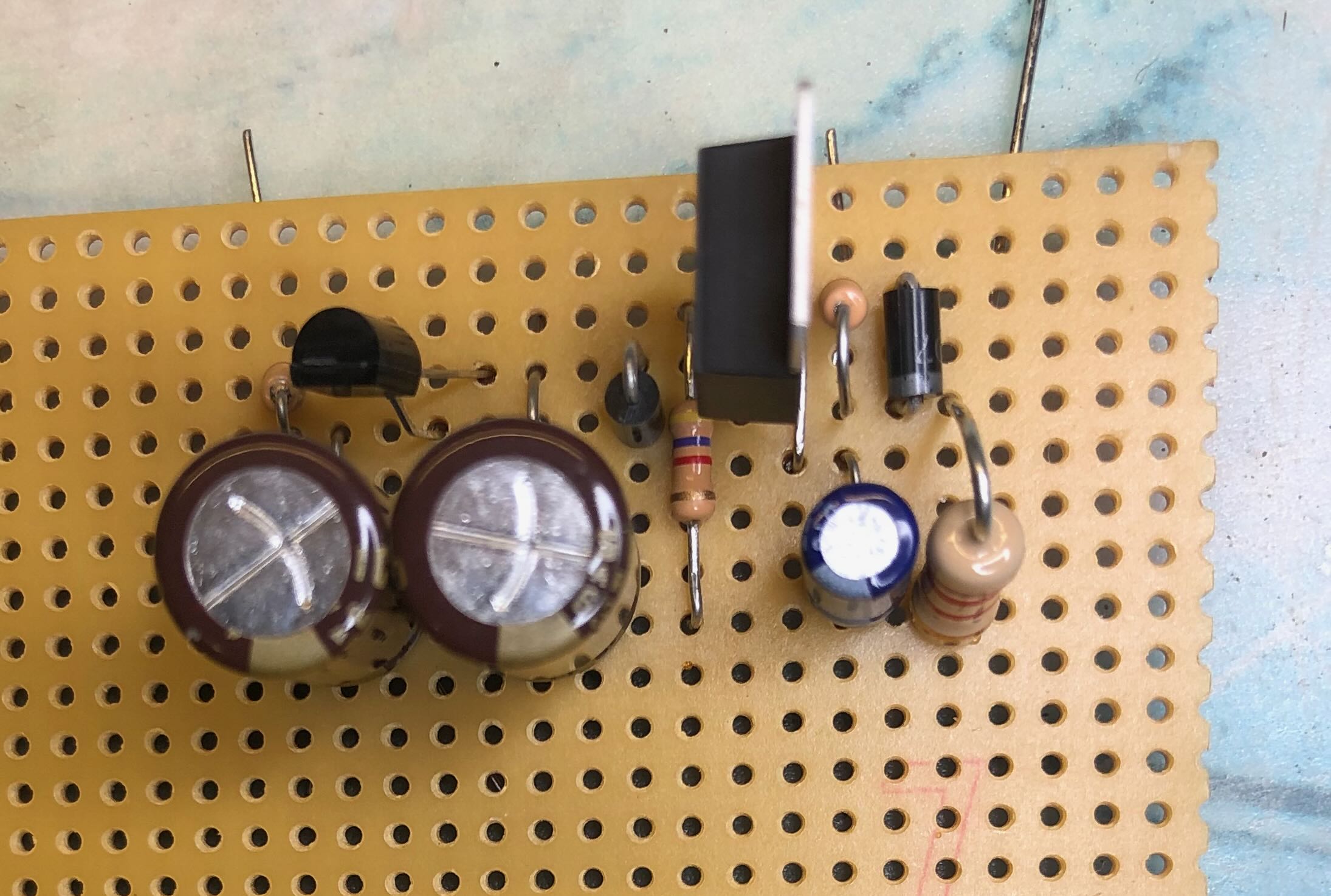
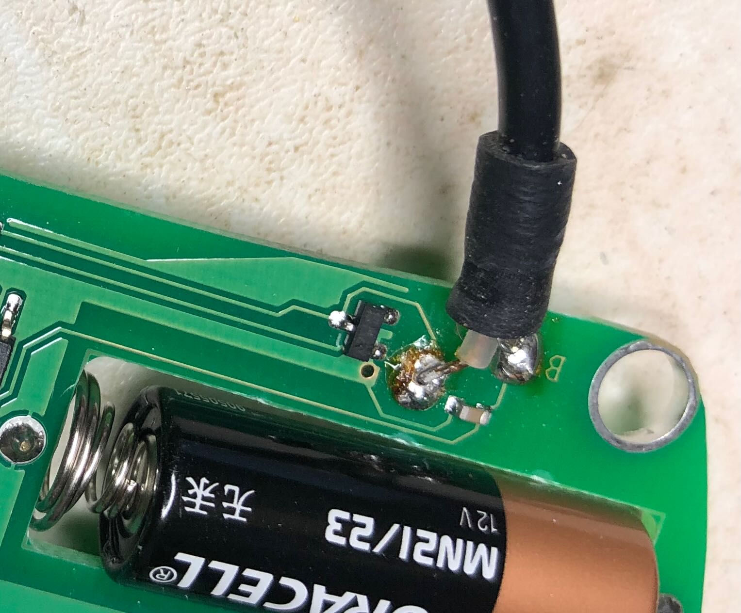
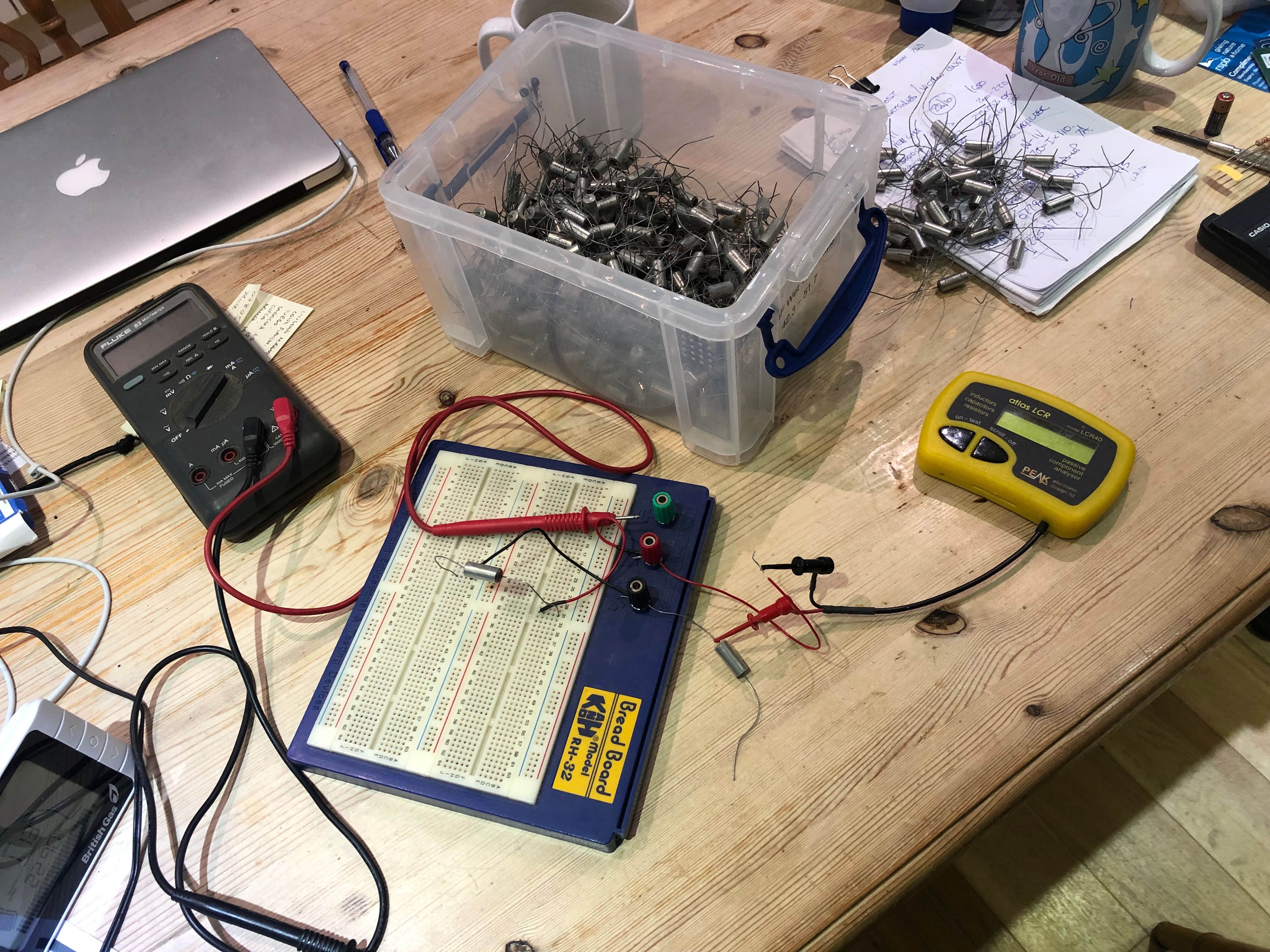
Decided to sort through the box full of tantalum capacitors looking for 20 over 49uF to use in parallel. Broke out the Peak LCR40 which, not surprisingly, needed a new battery and then wouldn't carry out a probe check........ Oh Goody I thought, fortunately it was nothing more complicated than the inner core of the coaxial test lead had come adrift from the PCB, one of the downsides of the cheap and cheerful Peak meters.

USlGFAs.jpg


Broke out the old breadboard to speed up the testing......

e5bR5Zn.jpg


I think I'll be outside shortly assisting SWMBO with the horses as they're hobbling over frozen poached ground again.

Regards

Richard
 
Good Evening All,

That's me making a start on the first pair of NCC200v1.5 PCB's:-

dVpehe9.jpg


My equation concerns R12. The PCB has a value of 3k0 so that is what I fitted but previously this has been the 2k74 RC55Y part as lying at the bottom of the PCB - which should be fitted????

Regards

Richard
 
Good Evening All,

Well that is two PCB's completed but for TR5 for which I'm waiting on the heatsinks.

I see that C14 in the 'old' Parts List is a 330pF device whereas the PCB details a 390pF device. I've attached a second 47uF tantalum capacitor on the bottom of the board so C6 is circa 95uF/ 50V.

7Ep6vZc.jpg


QFK8SKu.jpg


I've not fitted any Lucar tabs yet until I confirm what size are required.

Tomorrow I'll look to putting the HCR200's in to the oldest NAP250 as Stage 1.

Regards

Richard
 
Richard
If you have 2k7 RC55y then fit them, very nice quality resistors
There are various versions of the board and most have 2K7, ver 1 has 3K0 and NCC300 has 3K0 but IMO it will make very little difference, it is in the signal path though hence the RC55y
Here is the one from my old Voyagers

IMG_1651 by Alan Towell, on Flickr

Alan
 
Alan,

Thanks for the reply. I'll change them out. I think the heatsinks are en route to allow the next stage.

Still reading up on stuff. I noted comments around fitting JFET's in place of R21 which I think might be allied to the LED substitution 'thing' that came up at one point (Negative supply rail rejection???). I've directed an EM to Martin Clark.

Regards

Richard
 
The standard spade plugs are the quarter-inch variety (6.3mm). The old Naim amps used the smaller ones (2.8mm). I don't think they ever used the middle size (4.8mm). Ultimately, you can use any type that suits your fancy, but I generally prefer the bigger ones.
 
Good Morning All,

You know a simpler man than me could get very confused between the schematic and the PCB. The current schematic has four resistors identified as being RC55Y types yet the PCB also asterisks the TR1/ 2 100R emitter resistors R11/ 13............ LesW has, in the past, directed to be guided by the PCB...........

It's my OCD coming through!!

Regards

Richard
 
Good Afternoon All,

That's the 20off BUV20's turned up with the postman today. A random two showed an hfe of 38 and 39 on the Atlas DCA55 BUT the only real 'test:-

gMX9myI.jpg


Now to break out the glue and put it back together......... that really isn't the way to treat £8.43's worth of semiconductor.......

Regards

Richard
 
Good Evening All,

Just trying to get something done before Xmas proper arrives, first up a jury rigged soldered up TO-3 case:-

r2vKY1h.jpg


The NAP250 at the outset:-

JckPFlh.jpg


Regulator boards out:-

PvBUB1l.jpg


Old regulator boards:-

Yl0bPs9.jpg


Cleaned up:-

kRTliOT.jpg


Fresh heatsink paste applied:-

8DrSGU3.jpg


HCR200 installed, had to replace two of the Lucar connectors - not the best design job IMHO:-

4CWciVn.jpg


Two damaged Lucars:-

L7iemdf.jpg


That's 45V on each rail. Time to put the lid back on this amplifier for now and get it back in to the system.

Regards

Richard
 
Good Evening All,

I spent a part of this morning and evening putting the system back together again. The above amplifier was only working on one channel which was a bit concerning. I took the lid off again to find that the negative supply to one amplifier board had become detached somehow.........

The picture below is the 'mock-up' of the above Stripboard circuit, don't pay any attention to component values:-

7xttozb.jpg


Regards

Richard
 
Good Evening All,

Wasn't expecting to see +/- 116V (no load) coming out of the CAP 6? Will stick a resistor across it and see what happens.

Regards

Richard
 
According to the HCR200 Service Note, it can take as much as ±60VDC, so you've got just 2V to spare. As long as you're sure your mains won't float higher, you should be fine. According to that same service note, you can set the output voltage from the HCR200 at a maximum of ±45VDC, which is fine for the NCC200.
 
Good Morning All,

Doing some head scratching here as I can't quite see how the one CAP6 can work in a NAP250! All halt and time to seek advice!

Regards

Richard
 
It's just as if it were a mono amp, except that the supply is fed to both channels.

Run the loom down the middle to the front of the case, then along the front to reach all of the HCR200 inputs. Everything stars from the shared points on the output of the CAP6, which means you'll have 6 wires in that loom.

Of course, the HCR connects to the NCC200 board. Curiously, the HCR200 Service Note shows only one ground going to the input end of the NCC200, while I would have expected an additional ground wire from the HCR200 to the output end as well. You may want to call Les to confirm that.

As for the speaker outputs, of course the positives come from the speaker outputs on the NCC200s. The negatives comes from the "dirty" (input) end of the CAP6. Run those two wires above the top centre of the CAP6, then over to the back, and finally along the back end of your amp to each negative post. Alternatively, you could probably run them straight back from the CAP6, then along the back of the amp to each speaker negative post.

Is that clear?
 
Mike,

I've sent you a PM.

What I really need is a wiring out plan for the NAP250 transformer detailing which wire is which. It looks like red/ orange and yellow/ grey need to go to the A/C inputs and there is a green/ white wire which I believe are the CT's

Regards

Richard


advertisement


Back
Top