Good Afternoon All,
I've now taken the lid off my unserviced NAP250 and had a look see. It's one thing seeing it as a picture on a forum but that doesn't tell you everything.
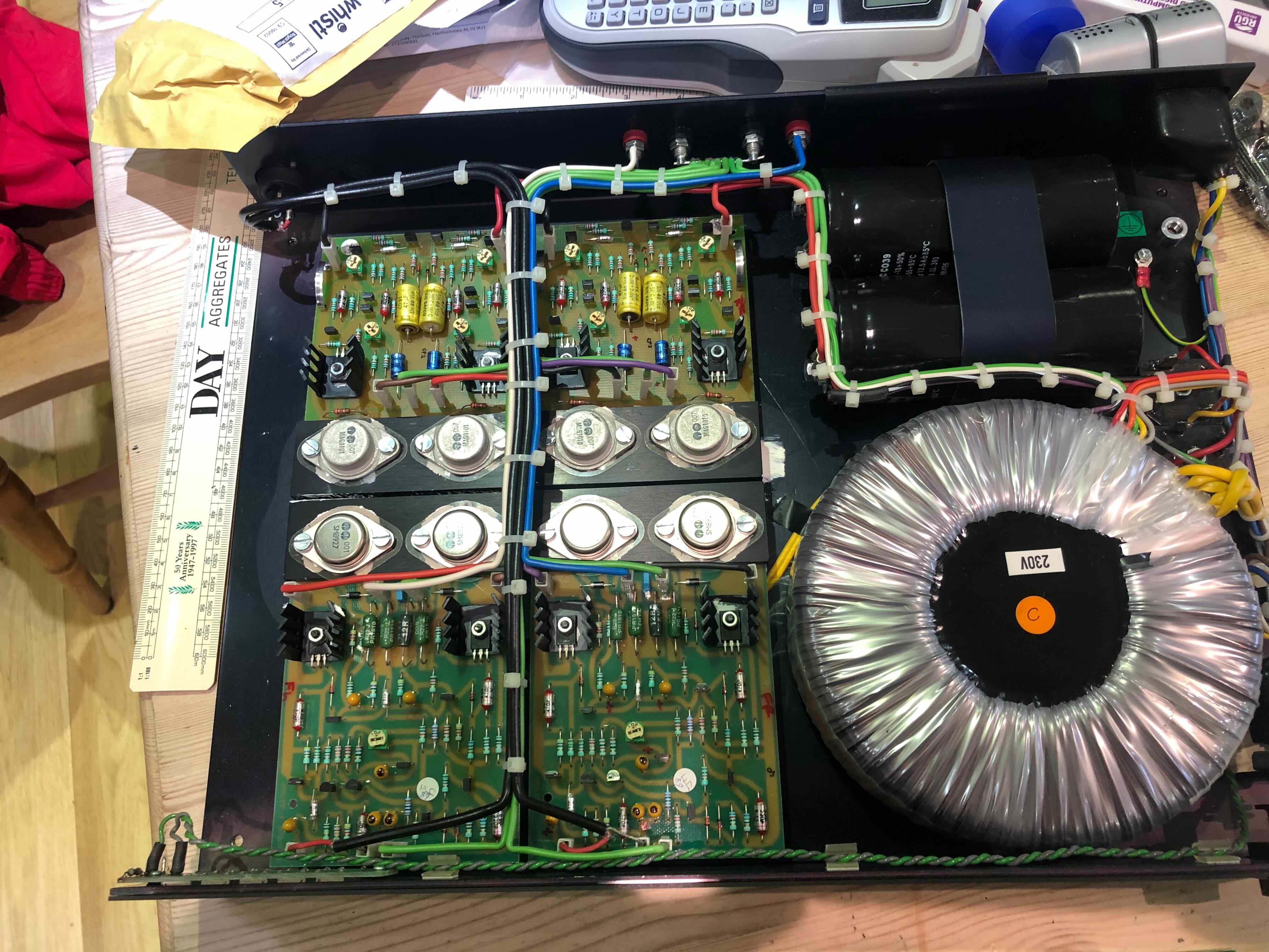
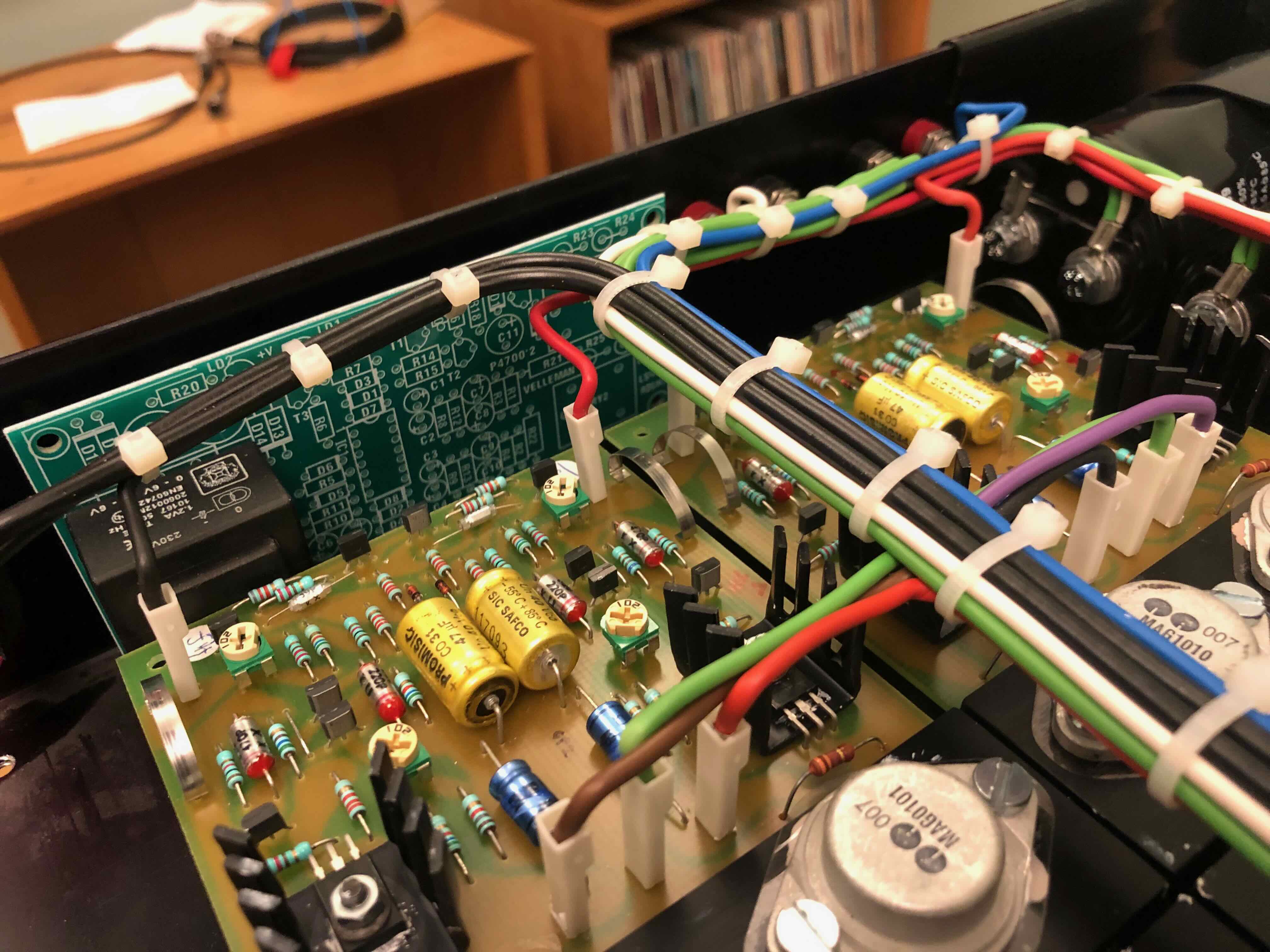
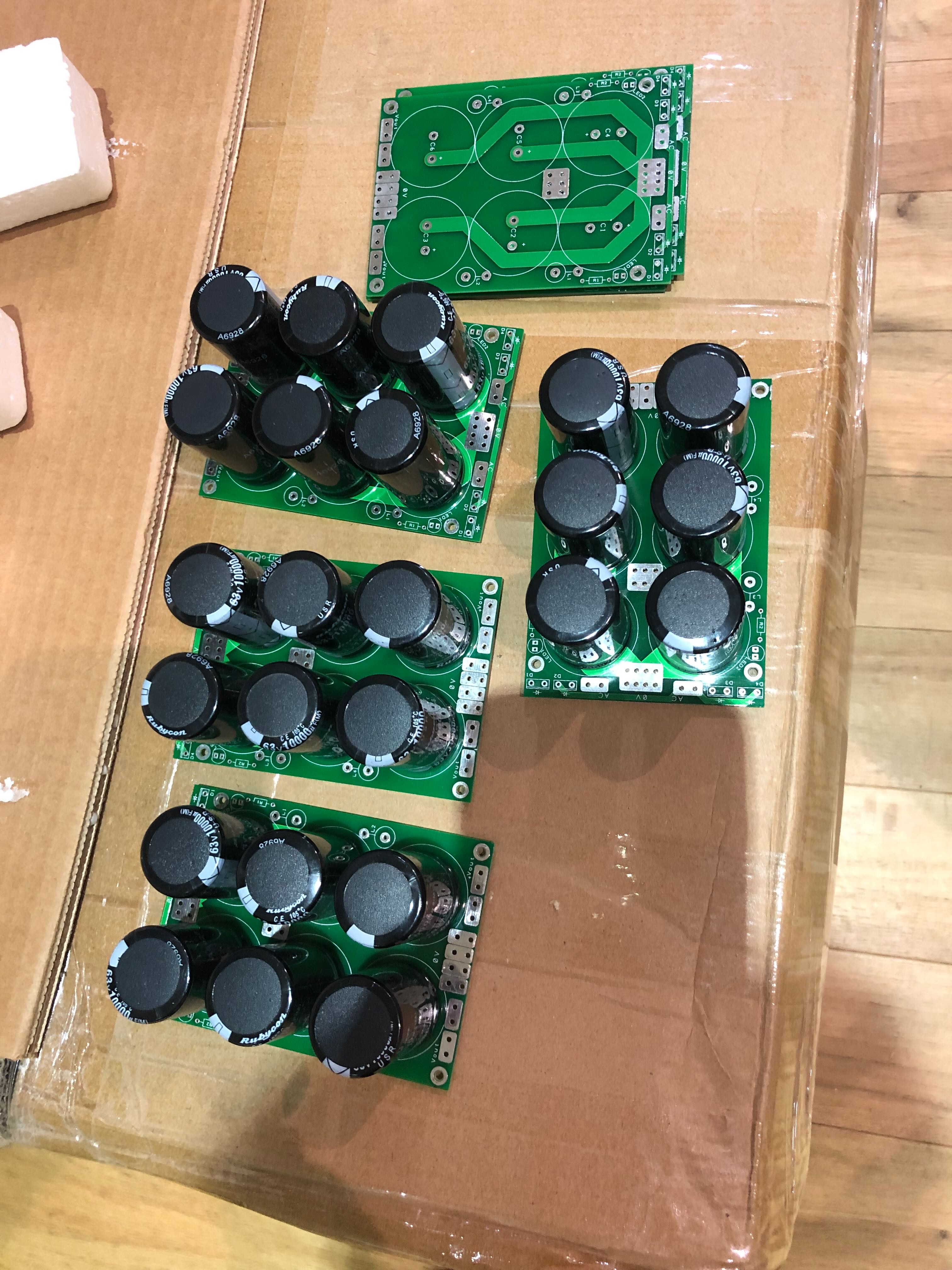
OK so lots of people will know what the inside of a NAP250 looks like:-
I can see no reason why all four boards can't be moved approximately 4cm to the left???
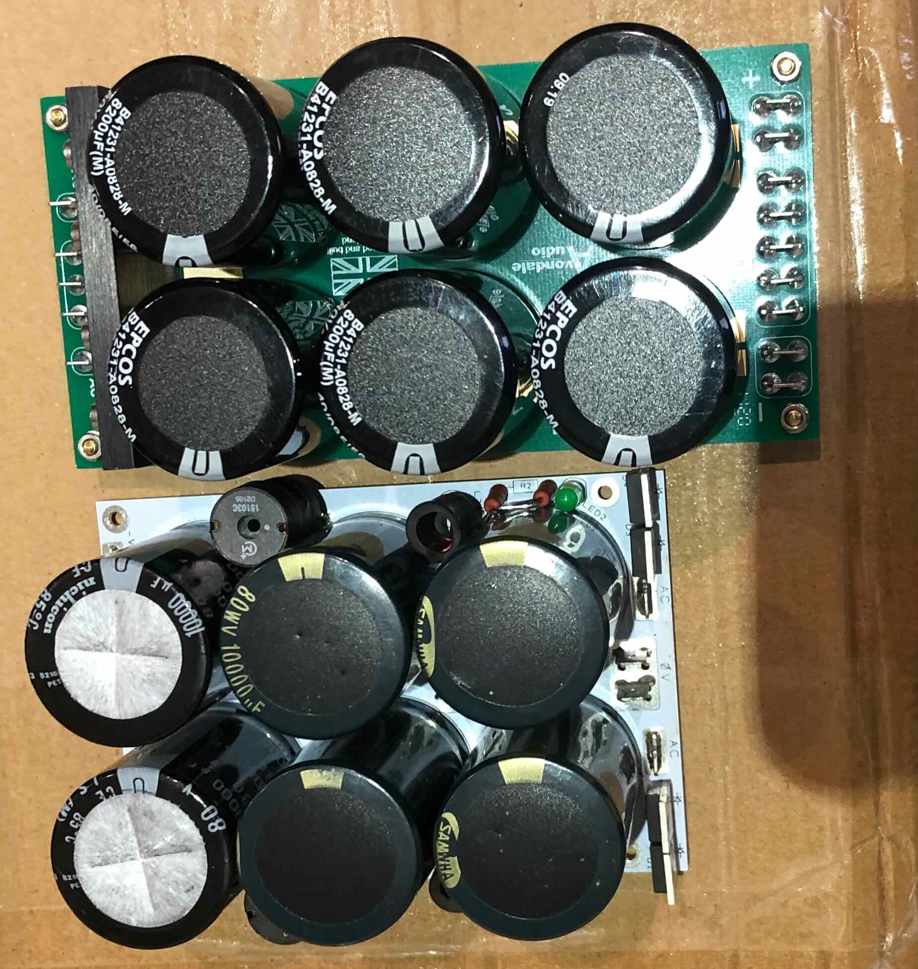
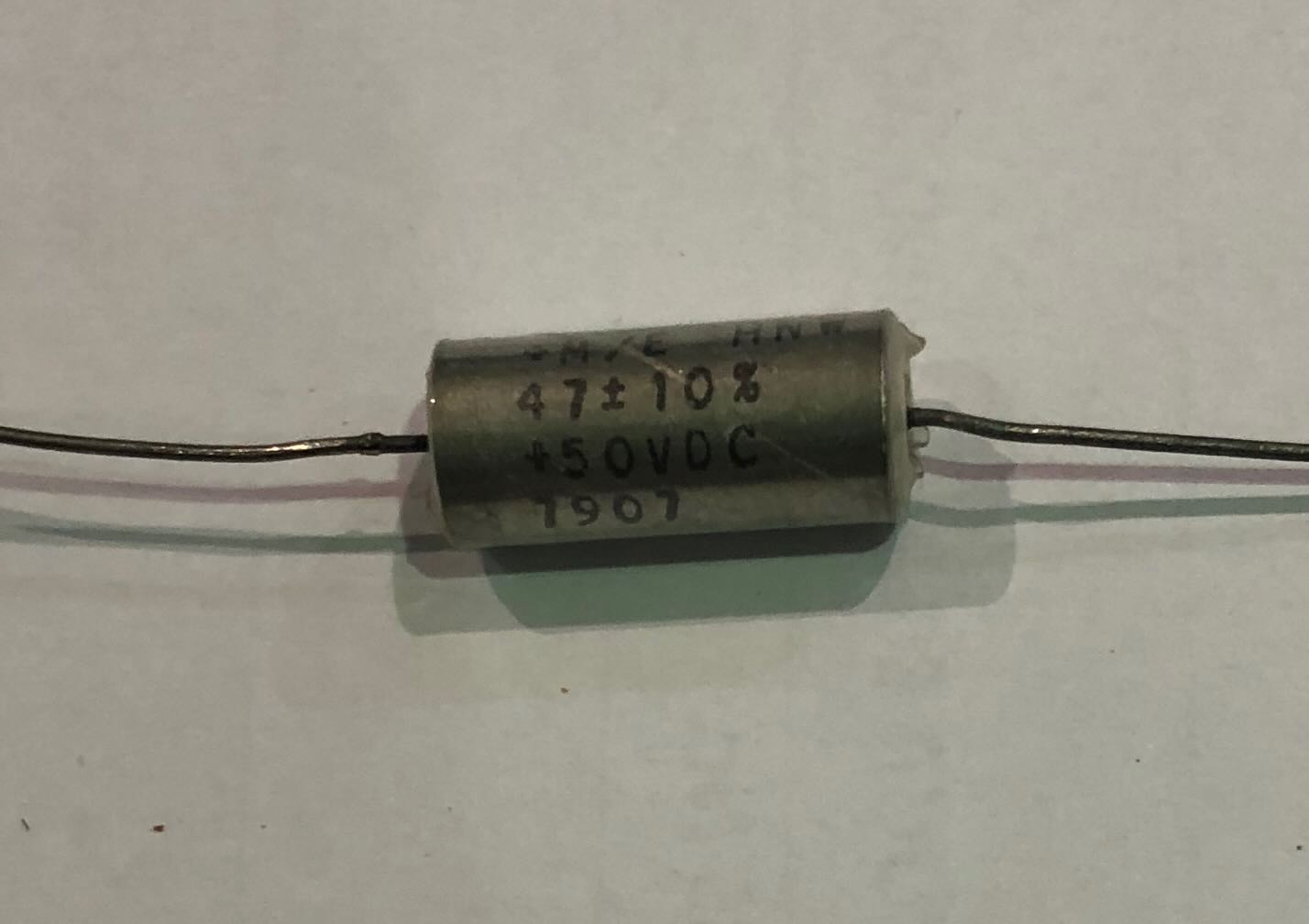
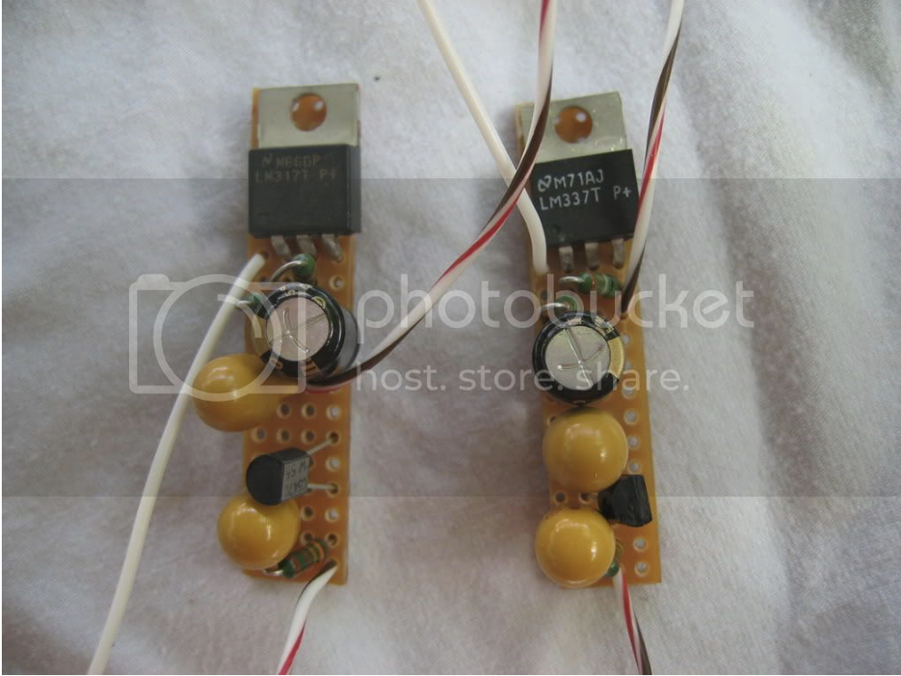
Next up is the difference in length between the Cap6 and the HackerCap, this amounts to circa 3cm:-
Theoretically that creates a potential circa 7cm wide space which could, I say could, potentially accommodate a transformer to power a VBE. Can anybody advise the size of transformer I believe LesW can supply?
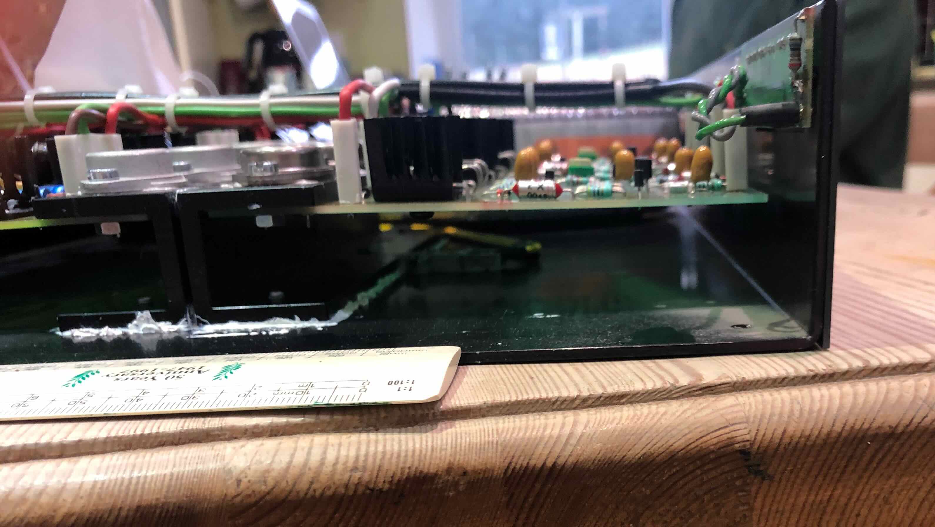
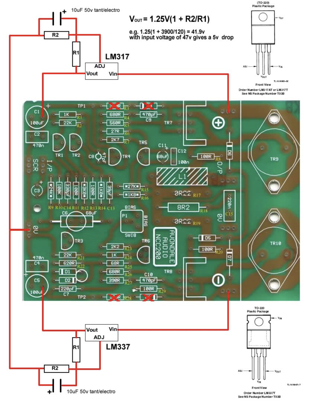
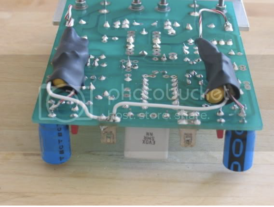
The next question would be "Where are you going to put the VBE PCB then?". A fair question but there is, I think, a possible solution. Take a look at this next photo:-
There is a space under the regulator and power amplifier PCB's. The overall height of the NAP250 internal space is circa 61mm. A NCC200 stands at 44mm and the existing space is 19mm high so this could be increased to a maximum of 36mm by using an (aluminium) spacer under the NCC200's. A VBE could fit in this space?
I have to ask a question here about exactly how much power the FE of a pair of NCC200 requires i.e. do you need a 50VA transformer or a VBE with a pair of MJ15003/ 4 output transistors???
It might be easier to fit a pair of SuperTeddyRegulators instead??????
Nearly forgot the one other board - the Velleman 4700. It is a tight squeeze but it does fit along the back panel. There is room to move the regulator and power amplifier's toward the front a few mm to improve things here but, again, this could fit under the power amplifier PCB's if raised?
Regards
Richard

")