advertisement


Courtiestown - Naim Amplifier (Avondale) Upgrade Project

Good Morning All,

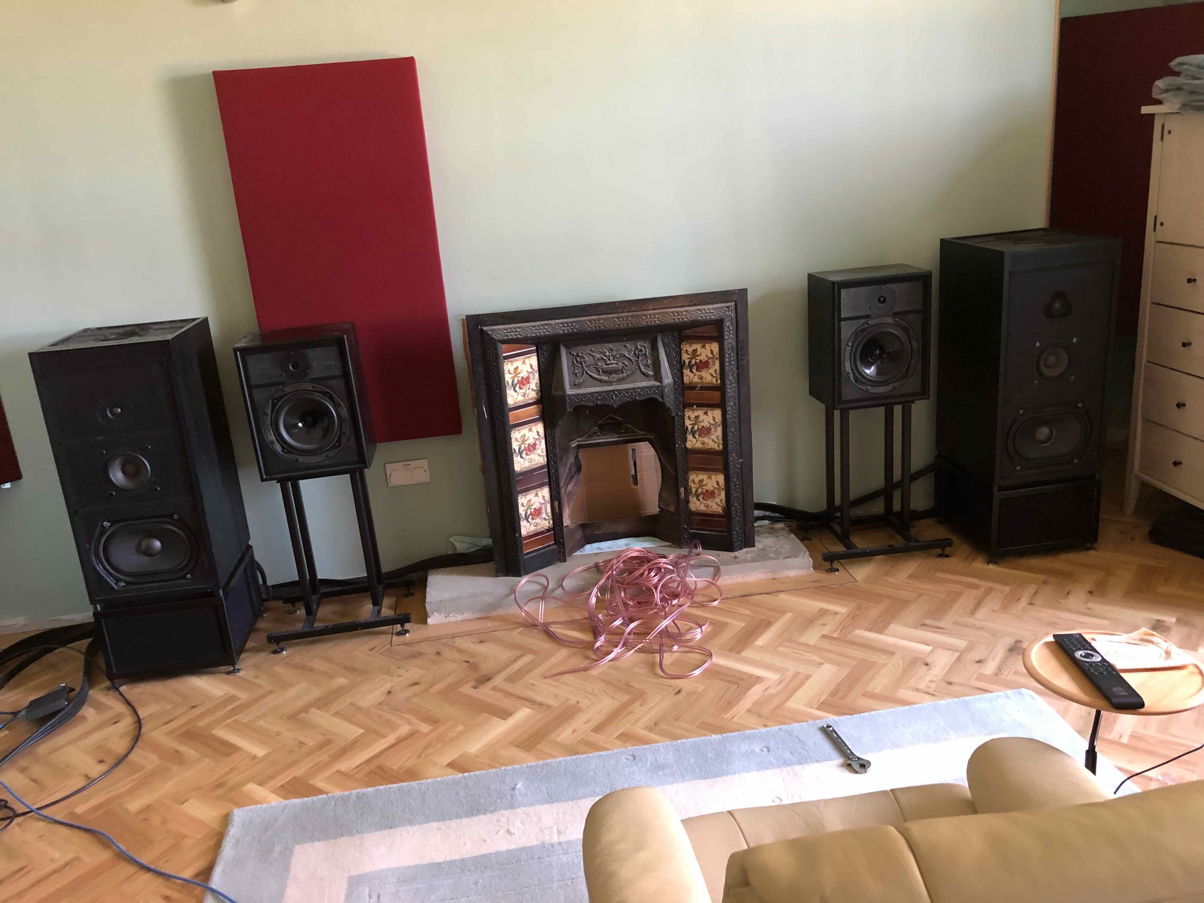
That's me back offshore again and hopefully we'll get this rig moved this week......

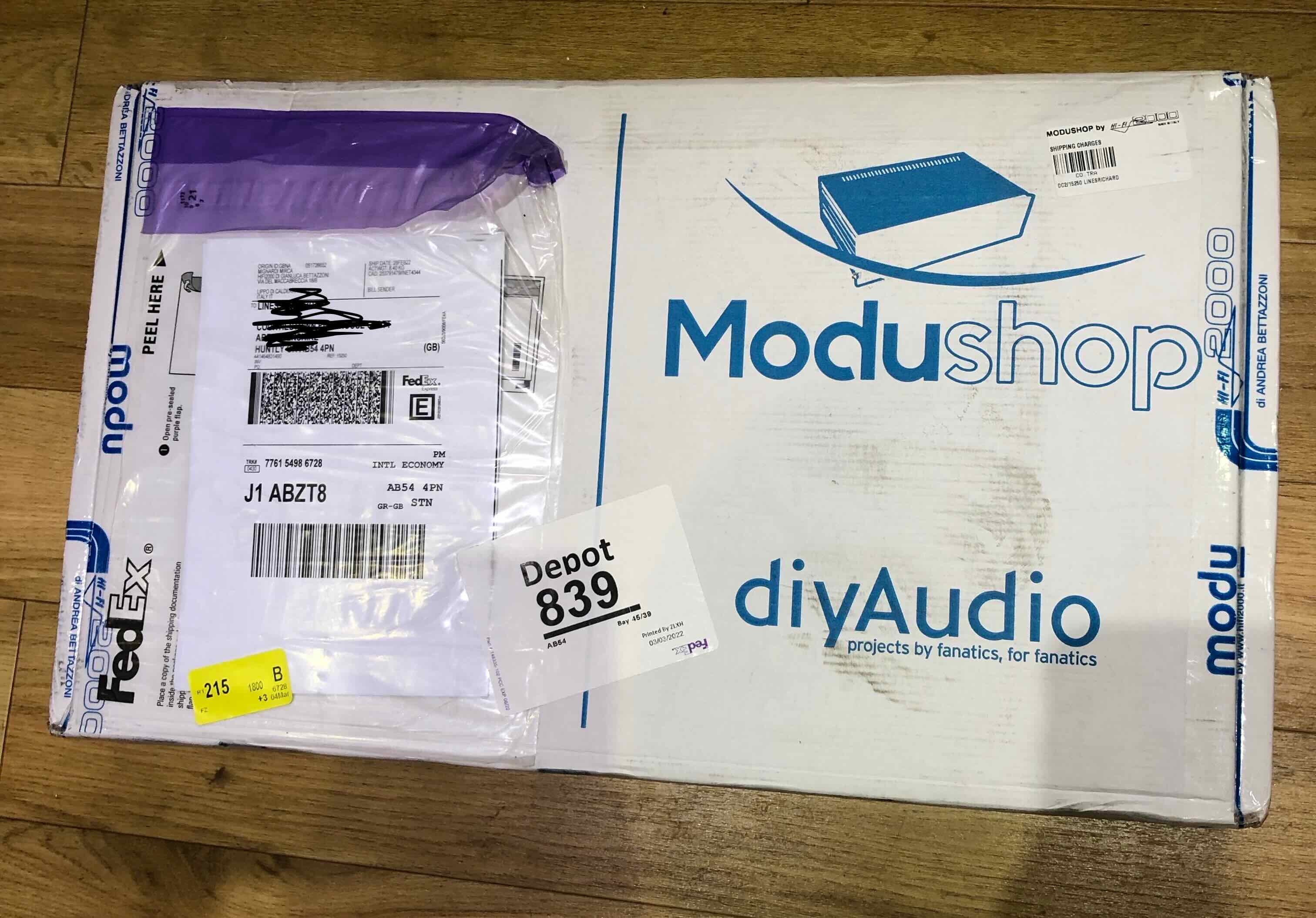
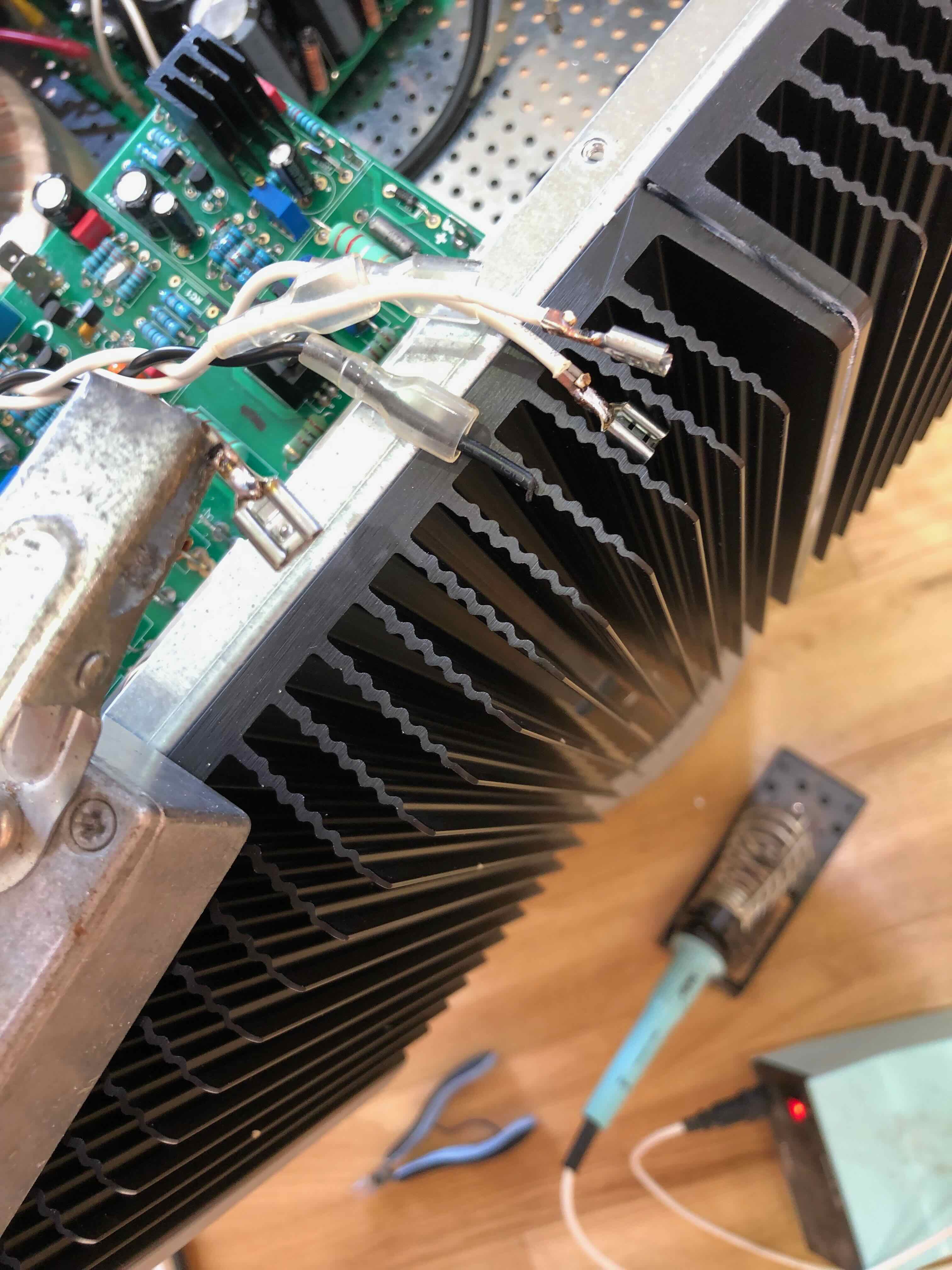
I've now ordered a second case from modushop to house the last Avondale based amplifier replacement.

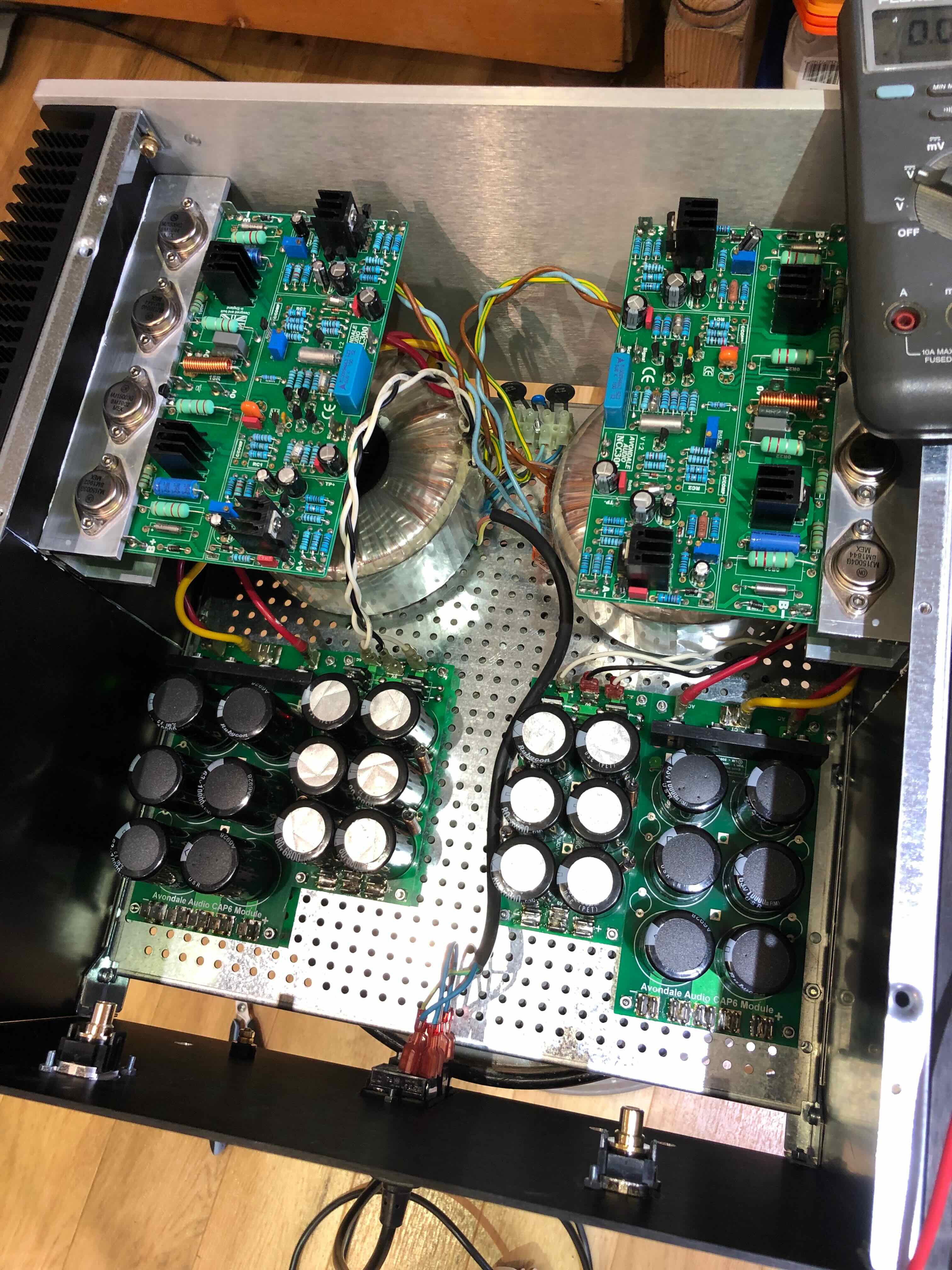
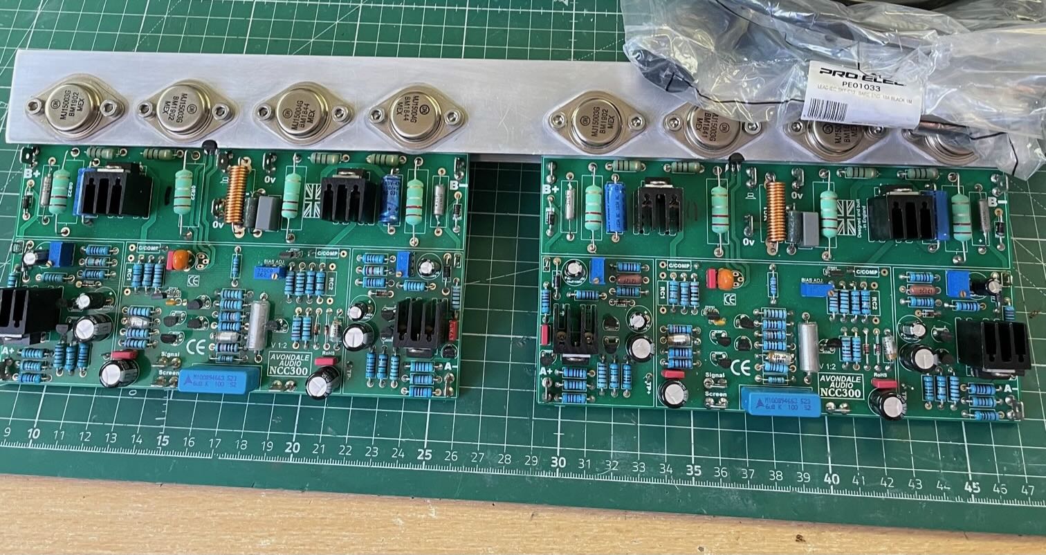
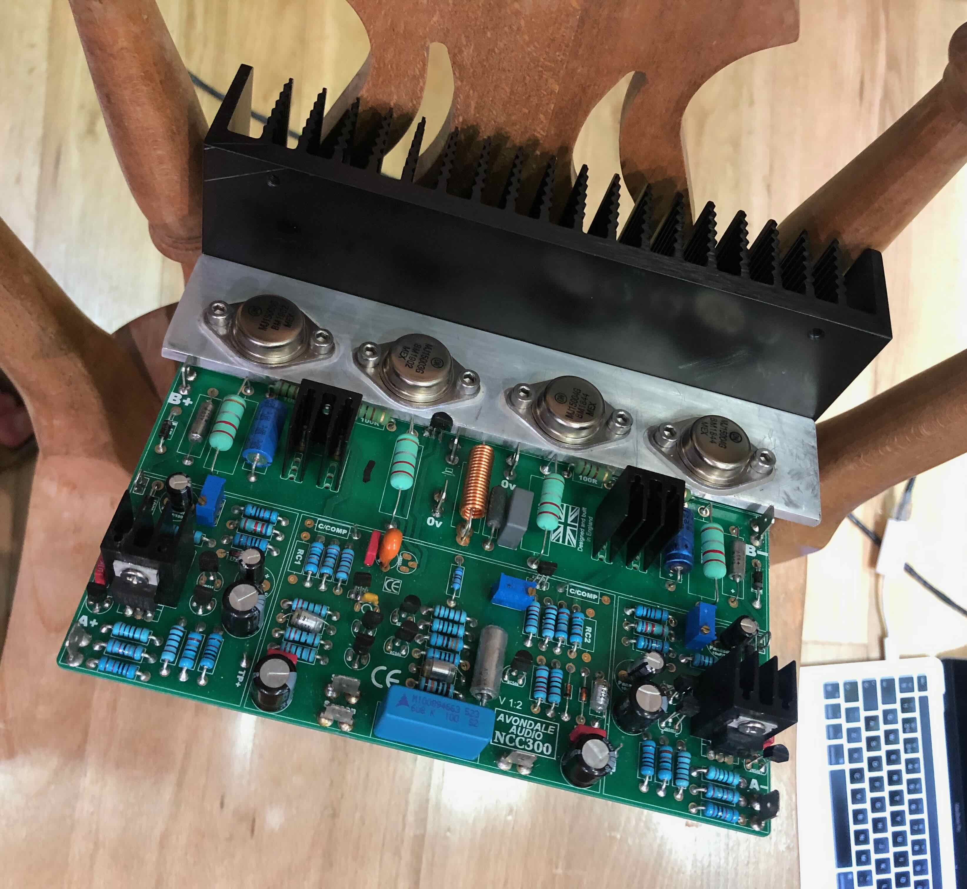
As stated above this project has gone ever so slightly 'off the rails' but in a positive way although there is also something of a downside. Things kicked off, not so very long ago, with the intention of replacing all 10 channels of Naim amplification with NCC200v1.5 board based replacements and all buying and sourcing efforts were focused to that end.

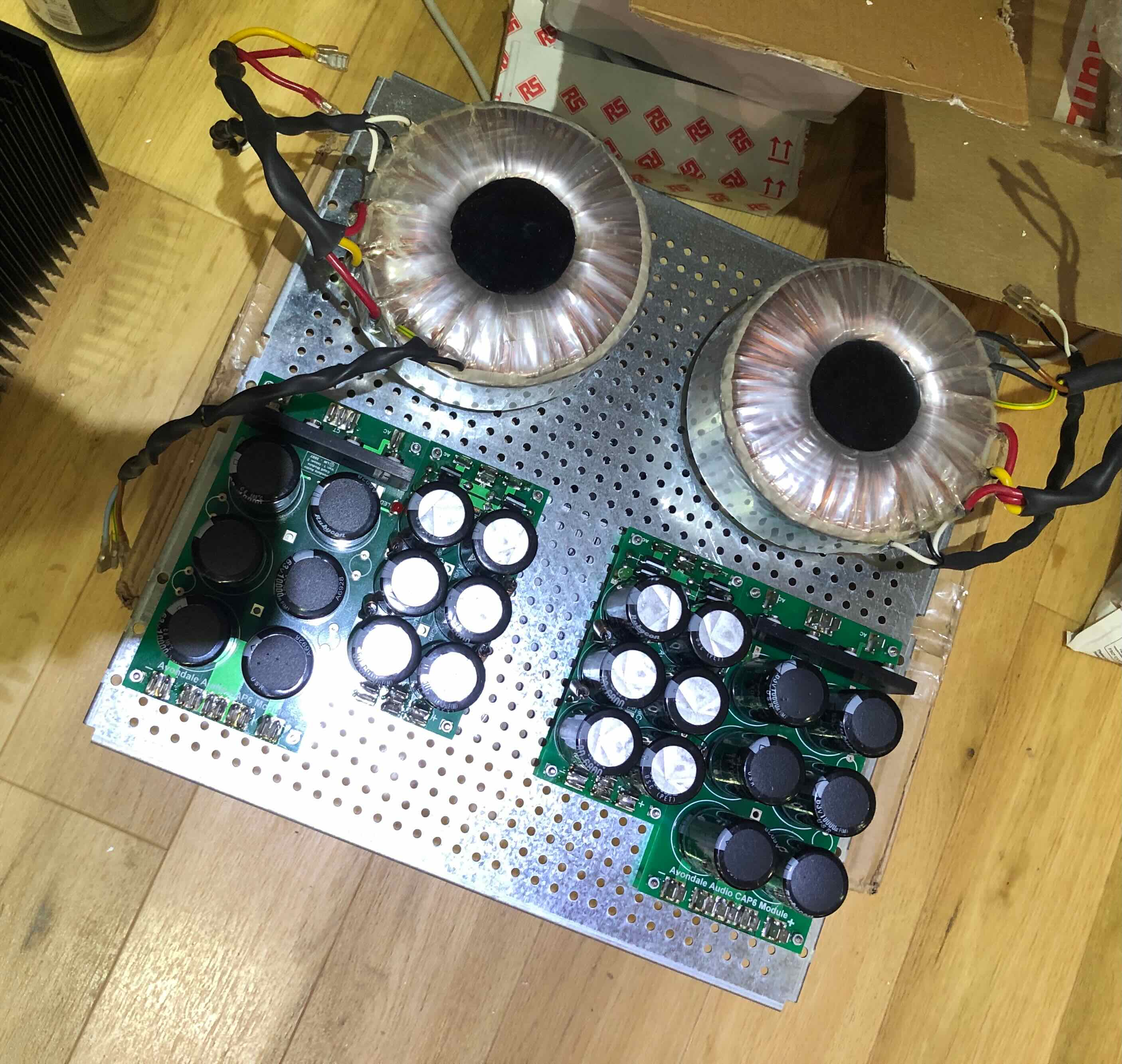
I now find myself with an excess of parts such as 6off complete NCC200v1.5 boards c/w parts (the original thinking being to benefit from 'bulk' purchasing), CAP6 PCB's and assorted parts, VBE PCB's and assorted parts and HackerCap PCB's. I have no idea what demand there would be for these but I will be composing a complete listing and posting it under the Classified heading in due course. All parts sold will be sold at the prices paid for them.

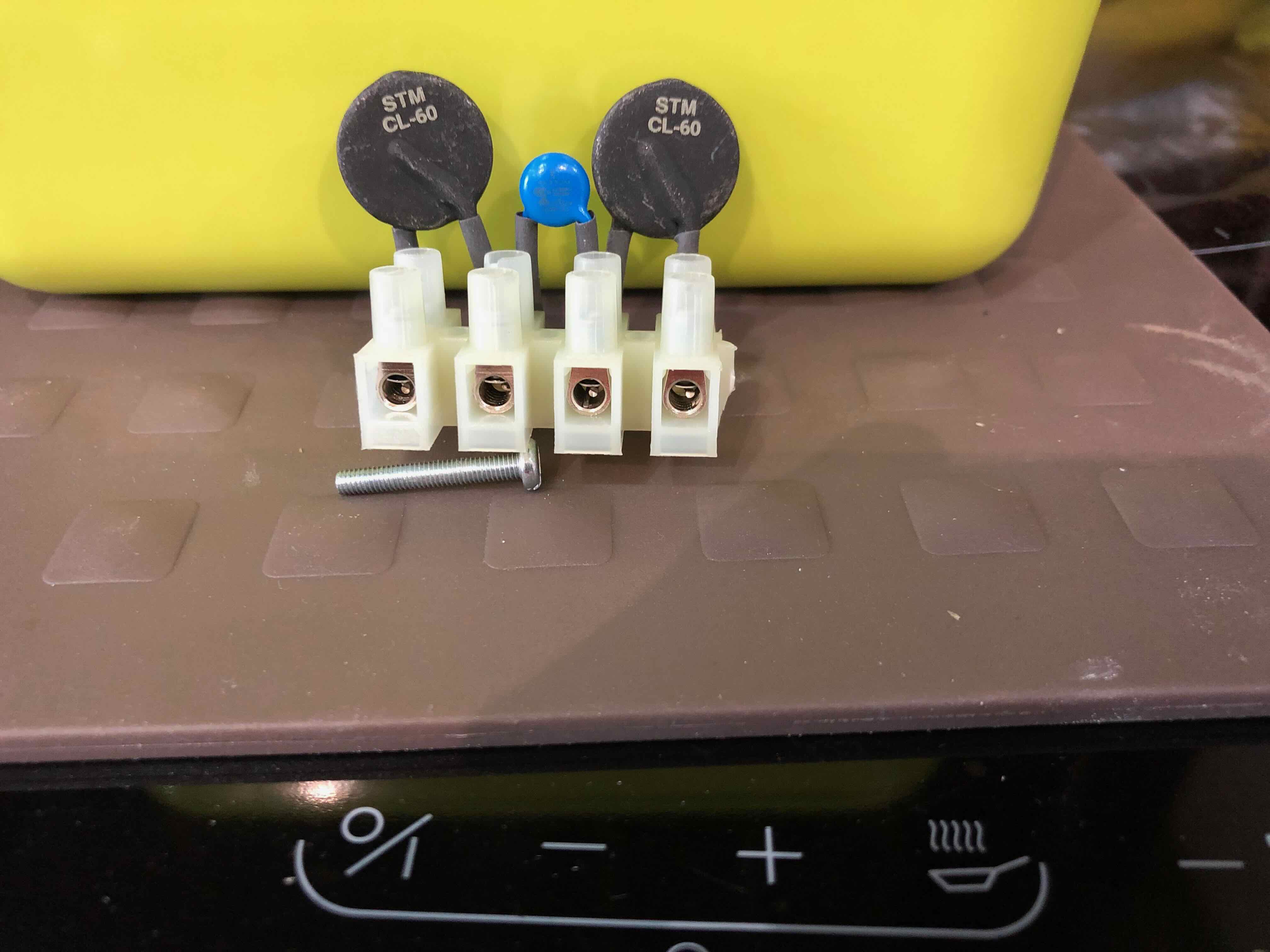
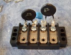
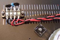
Following a conversation with Graham I'm going to be taking a somewhat different route regarding a 'soft start' system. I'll be using https://uk.rs-online.com/web/p/thermistors/2104325 CL-60's in conjunction with a suppression capacitor:-

DPyj7qN.jpg


jUekHfk.jpg


Regards

Richard
 
Last edited:
Good Morning All,

I have a simple question this morning.

What push fit connector do people advocate for use with the likes of pins on the Velleman speaker protection board?

You can buy 1.0mm and 1.3mm pins for inserting in Veroboard but there doesn't seem to be a readily available push fit connector to go with them.

Regards

Richard
Those pins are the one thing I hate about the vellaman speaker protection boards, I bodged my boards and installed male spade connectors
Alan
 
Good Afternoon All,

I have sent an EM to Vero asking the question but can see I might have to look at fitting such as 2.8mm Lucar's........

Regards

Richard
 
I should do that too...those pesky pins are a pain.
Yes indeed. I've made a second board (with relays on it) with spade connectors (normal ones with two legs). I guess the easiest way is to change to one-leg spade connectors.
 
Good Evening All,

That's me back home again.

The two 500VA Canterbury transformers have arrived from Portugal:-

3K5J2NX.jpg


Work has started on fitting things to the base plate for the stereo NCC300 'Voyager':-

gxO75eM.jpg


The NCC300's arrived bolted to a common heatsink:-

Gob3JfL.jpg


This has now been cut in half and one 'half' bolted to a heatsink before I ran out of time:-

6ztWw9g.jpg


Regards

Richard
 
Last edited:
Good Lunchtime All,

This is where I'm at circa 1200 today:-

v4ZDYar.jpg


Thank God this isn't arriving until Monday :rolleyes:, I am grateful but Fedex really do need to work on their predicted delivery times :-

88OfLsv.jpg


I was due away on the Tuesday but it looks like next weekend now so there will be time to build this other amplifier.

Cricklewood have been very efficient, the ZTX753 I ordered yesterday are here already, that's pretty good considering our rural location and only Royal Mail (albeit Royal Mail 24 delivery).

Regards

Richard
 
You decided to put the transformers under the NCC300 modules. Hopefully they don't have an impact on the boards above. It's probably fine.

Pondering it, could you mount the CAP6 on the heatsinks, in line with the NCC300? If so, then you could have the transformer sit below that, feeding each output stage. Then the Mini-Caps could site side by side near the center, under the NCC300s, to feed the input stages.
 
Mike,

I'm not anticipating the proximity of the transformers to be a problem, they are further away from the transformer than a board in a NAP250 after all.

To one and all - OK hands in the air for the latest error. The case I've ordered from ModuShop isn't the one I thought I'd ordered so the one I have will be getting put up for sale shortly in the hope somebody can make better use of it than I can. I have no idea what I was thinking when I ordered it, essentially it is only 300mm deep rather than the 400mm I need.........:oops::oops::oops::oops::oops::oops:

Will shortly make a start on wiring the amplifier.

Regards

Richard
 
Last edited:
Richard
What size case is that, I might be interested, my power mossfets finally turned up after 9 months waiting so case is the only thing left.
Geoff
 
Good Evening All,

Well I was going to do some more on the latest amplifier but after helping Kate doing horsey things earlier I decided to sit in the Hi-Fi Room and do some listening whilst Kate gets the foal ready for a show tomorrow - apparently I've volunteered to help??????

Got this done earlier:-

B9hvkw2.jpg


It's now bolted in to the case. More tomorrow.

Regards

Richard
 
Good Evening All,

First up a gratuitous horsey shot:-

2zOKXfn.jpg


Getting back on subject this is a photo of the amplifier as it stands currently:-

VTbc3OP.jpg


Yes the wiring is a bit higgledy-piggeledy but it is functional. Although it isn't immediately obvious I'm using those 5 way connectors to split the incoming mains to both transformers. The mains earth is bolted to the subframe along with the screens from both transformers

Two issues I need to investigate before going further:-

1. the LED's on one CAP6 don't light up and I'm sure they were both wired the same - maybe not and

2. the more important odd result is the voltage coming out of one MiniCap6. I have ± 58V coming out of one but the other has a circa 27V/ 89V split which had me scratching my head a bit???????

I'll be disconnecting the input to the 'rogue' MiniCap to check what voltage is going in but other suggestions welcome.

Edit - I've just had a quick check on the transformer '42V' output and am getting some odd low voltage readings whereas the other transformer is showing ± 43V - I'm a little confused currently. Just about to break out A.N.Other transformer.

Further edit - the transformer is giving out ± 42V but there is something funny happening as the DC output voltages, on the MiniCap6, change with one side dropping and the other rising...........

Regards

Richard
 
Last edited:
Disconnect transformer secondary's and check all outputs AC without load.
Check all your wiring from transformer to rectifiers?
then check the rectifiers them selves, orientation, soldering and with a diode tester
Check smoothing caps, orientation and soldering, check for solder short's
Alan
 
Alan,

Thanks for the suggestions.

I removed the MiniCap6 last night and gave it a dose of physical examination. There are no obvious soldering issues and there is continuity where there should be continuity. The components, save the LED and load resistor are brand new (yes that doesn't mean that one, or more, aren't faulty) so wouldn't be my first suspicion.

It is the result from the transformer which has me slightly confused. When I had Kate hold the three 42V secondary lead wires whilst I measured them I got the 'odd' low voltage readings. Later when I rechecked them it showed the expected 42 - 0 - 42V.

I have just connected the 'suspect' 42V output from this transformer to the other MiniCap6 and I'm seeing the same result i.e. wandering output voltage.

Just to confirm I re-connected this other MiniCap6 to its original 'proper' 42 - 0 - 42V output and it is giving me a steady circa 58V on both sides.

Clearly(?) there is something awry with the 42 - 0 - 42V output on this transformer. It is a genuine Canterbury. Fortunately it is one of four so I'll try another. I suspected this last night and had made a start.

PmZYQAg.jpg


One thing that seems odd about all four of these transformers is the gauge of the wiring for the 35 - 0 - 35V output, it is way more heavy duty than the input wiring?????

Regards

Richard
 
Pete,

Good call, I should have been on to this given I had inconsistent results measuring the voltages out.

Re-crimped the connectors and then set about soldering for good measure - as I was soldering the 0V (black lead) it came apart from the connector............

I was going to post a picture but I'm uploading 17+ minutes of iPhone video from the horse show yesterday and our remote internet access won't handle it.....

That's the 0V lead with a new connector and tested out - all OK.

Photo finally loaded:-

FIC3D98.jpg


Regards

Richard
 
Good Morning All,

Thought for the day. I'm looking to replenish my stock of simple Ms x 20mm machine screws. Do RS really need t go to Japan to source these - https://uk.rs-online.com/web/p/machine-screws/3180610/. ???? :(

Currently engaged in boring domestic cleaning tasks but needed to move the Sara9's down from the back bedroom (the better for getting the vacuum cleaner in).

This is them sort of getting set-up in the Hi-Fi Room:-

KRmT30Y.jpg


That's the speaker cable what I bought off Sean from his recent advert.

I know considered wisdom is that you shouldn't have more than one set of speakers in a room at once but there is no way I'm moving the Isobariks out.

I'll now a step closer to being able to do some direct listening to different amplifiers.

Regards

Richard


advertisement


Back
Top