
Richard Lines
pfm Member
Good Morning All,
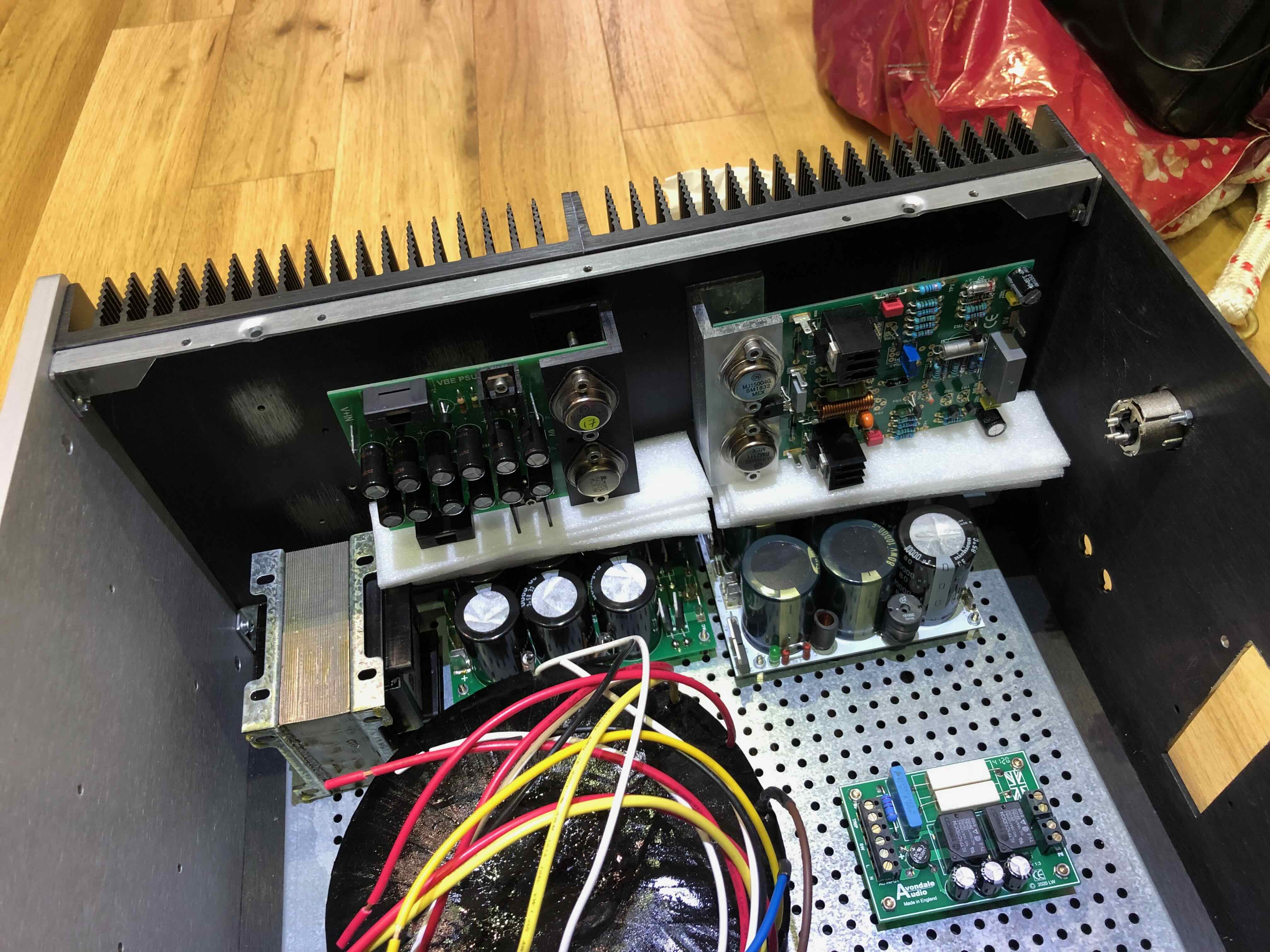
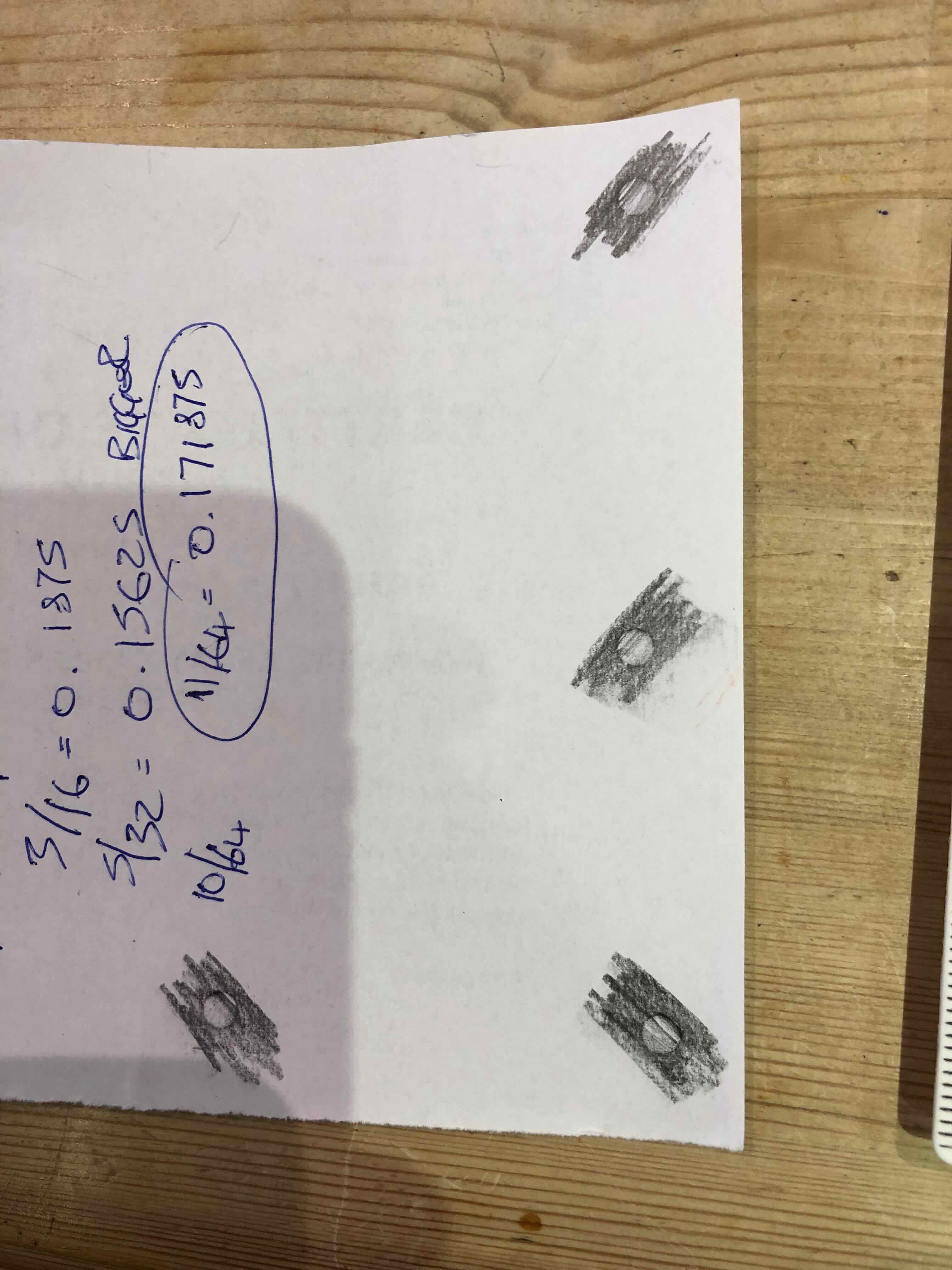
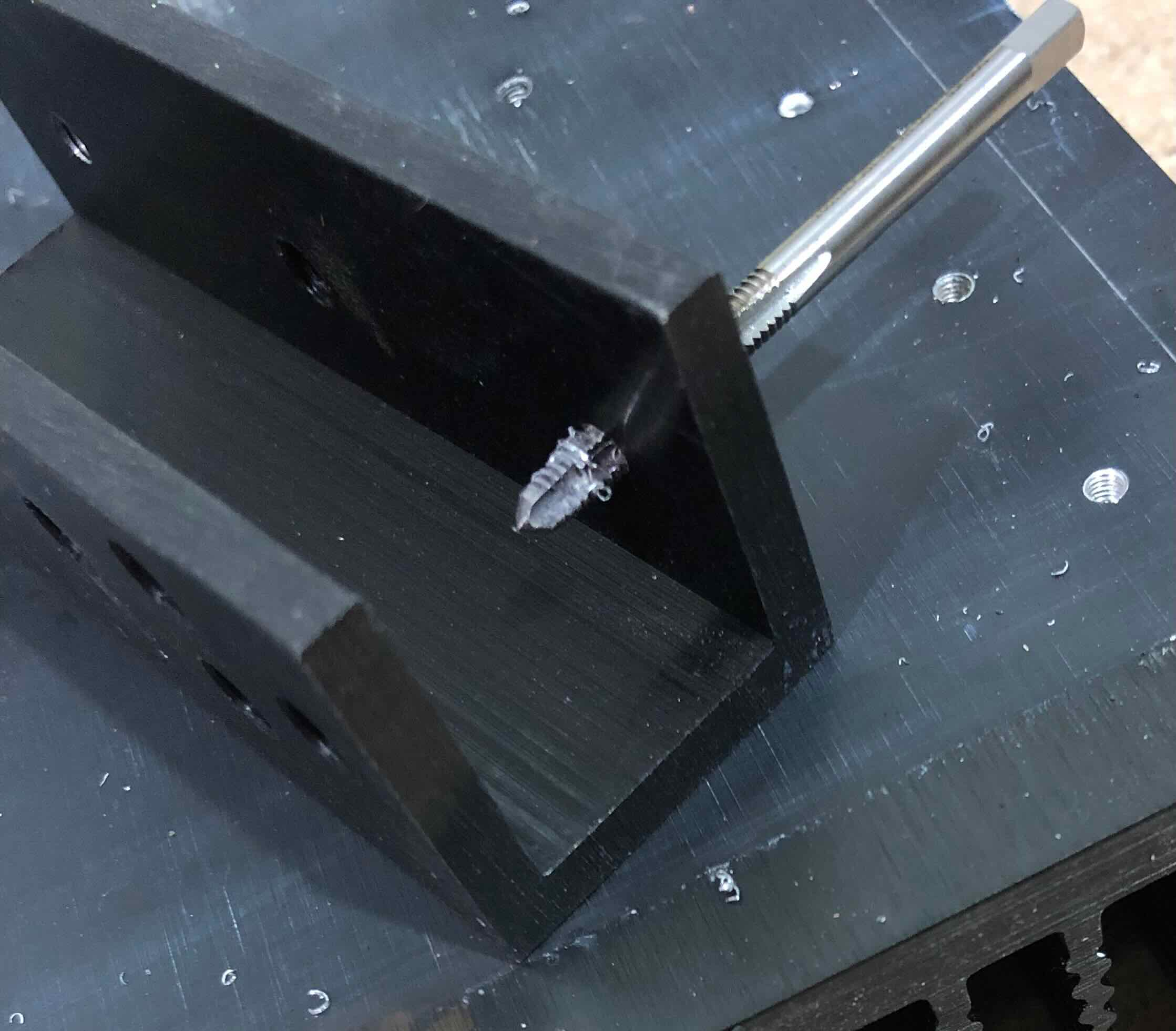
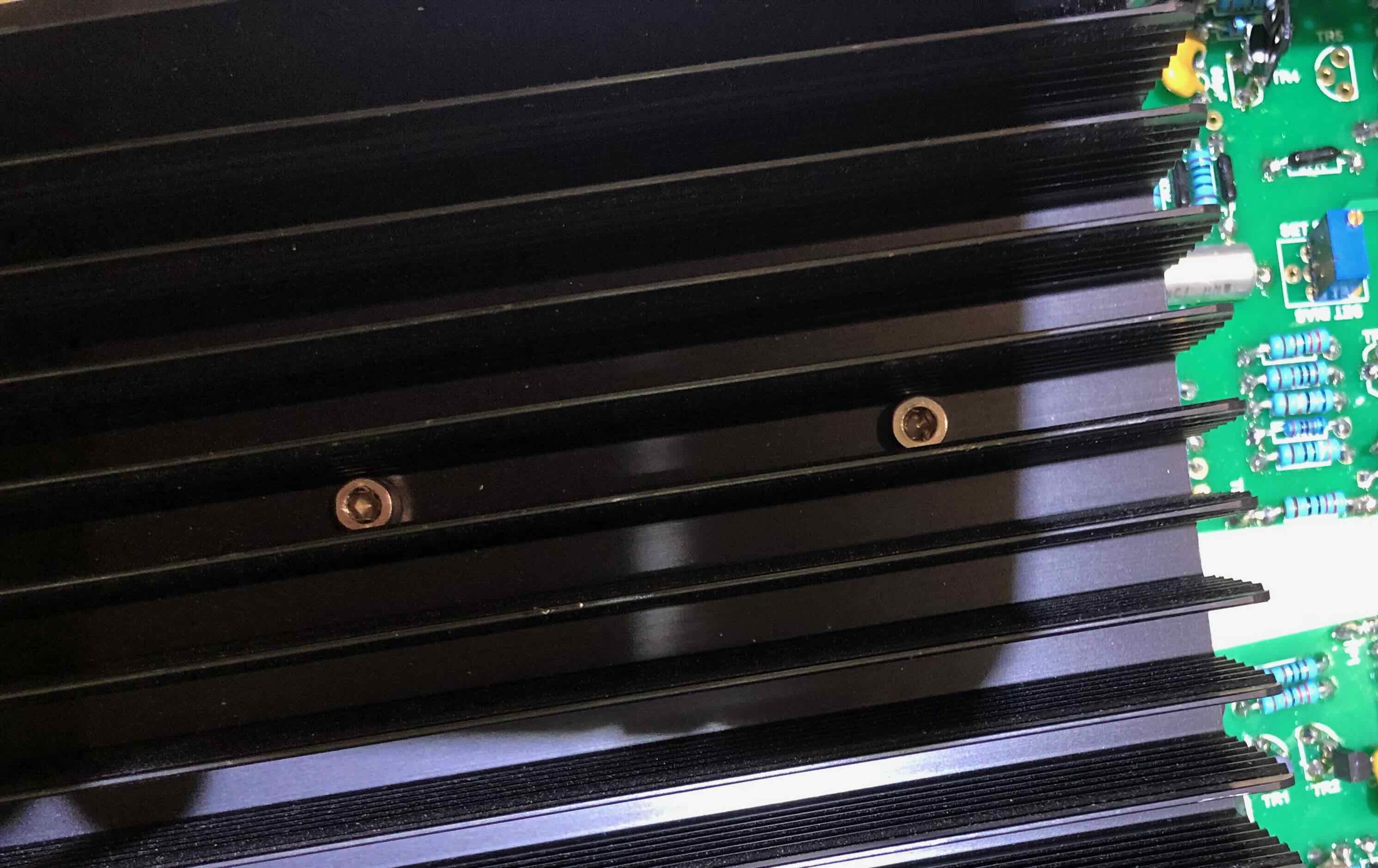
Today's stupid question - What are the two thread patterns in the Naim heat sink?
Regards
Richard
Today's stupid question - What are the two thread patterns in the Naim heat sink?
Regards
Richard
")

 voyager 10