advertisement


Contaminated Class A Amp

S-Man

StrivingON
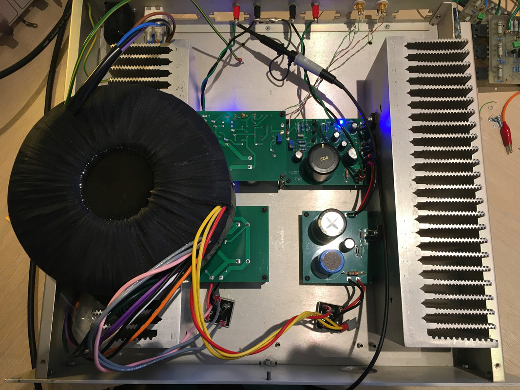
Here is my latest project:

IMG-1582.jpg


It is a single rail high bias class A/B mosfet amp.
It runs at 0.5A quiescent current, so it's "pure" :rolleyes: class A up to only about 1A. Hence it's "Contaminated" :D.

The schematic can be found in post #180 here:
https://www.diyaudio.com/community/threads/25w-class-a-amp-with-lateral-mosfets.183482/page-9

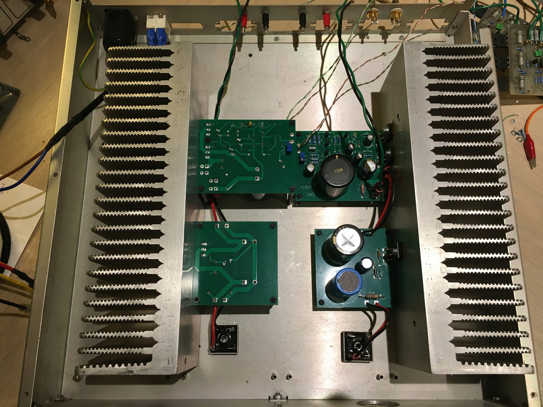
It's been running on the bench PS where I had to sort a couple of bugs. It's now ready for final wiring into the test mule chassis. Although I seem to have overlooked a key detail :oops:.
The heatsinks have been repurposed from the Aleph5. They are actually a bit OTT for burning off 20WPC.

It's supposed to be a very fine sounding. I expect I will find out soon.
 
Dan, I need to get it working reliably before any refinements.
It seemed to work OK on the bench after changing the compensation but has bursts of spurious oscillations when plugged into the system.

The designer insists it's stable. It has non of the usual input filter, zobel or o/p inductor. He says these are deleterious for sound quality. I think the amp will sound shit if it's oscillating or if it takes the tweeters out!!
 
Hmmm it shares a lot in common with my own latest design that's been in use here for a little over a year so far.

Mines uncontaminated class A lol but uses lateral mosfets, single rial PSU, capacitor coupled output and feedback from both sides of output cap in the same ways as this one! It's quite different in other areas though.

The bias setting looks a bit hit and miss here!

I'll be interested to hear your opinions on it S-Man:)

Surprisingly the bias with a blue LED comes out at 0.5A on both channels. I have space on the board for diodes in series with (other colour) LEDs to achieve other currents.

What quiescent did you choose for your amp? At what rail voltage?
(This one is NOT 25W as it claims, unless the designer means into something other than the usual 8R).

Any comments on the compensation method (the 10pF cap across the feedback resistor)?

Mine uses about 1.5A as it's designed to maintain class A to less than 8R loads. Rail is about 35V and it gives about 16.5W into 8R. It uses dual die mosfets. It is monoblocks with around 120VA transformers. I designed it to have very good voltage compliance to maximise output power for best full power efficiency.

There is a "hidden" compensation going on in your unit from the high impedance of the Vas into the Cgs of the mosfets.
A bit of a nod to NAD in the input stage there! Rather more advanced than NAD though.

Interesting things are possible with that dual feedback around output capacitor;) Bass can be "tuned" and damping factor can do a Buzz Lightyear... to infinity and beyond!
 
Hmm thought I had popped something. I forgot that the PS is connected with the hot terminal being 0V for the amp and put the oscilloscope earth on the cold terminal of the PS. The fault current was limited by a 15R resistor in my electronic crossover and various lead resistances, so no harm done :eek:.
Before my faux pas I had noticed that the amp oscillated when both inputs were connected.

Anyway the hair shirt contraption is back on the bench and my careful monitoring has kept my OW1 voice coils intact!

I think the amp is going to need an input filter because it bursts into oscillation if an input is touched. I realise that this causes noise, but it shouldn't cause oscillations. I actually used 499K for R1 and R2 because I was wary of the 1Ms in the schematic. I guess I could try 47K for R1, but the input cap would need increasing if R2 is reduced.

I have a feeling I will end up with the full set of "real world" interfacing components. Ensuring the safety of my expensive tweeters is far more important than some hair shirt minimalist idea of tweaking an extra iota of audiophiliness!
My 3 favourite amps seem to sound very fine despite these hindrances.
 
Mine uses about 1.5A as it's designed to maintain class A to less than 8R loads. Rail is about 35V and it gives about 16.5W into 8R. It uses dual die mosfets. It is monoblocks with around 120VA transformers. I designed it to have very good voltage compliance to maximise output power for best full power efficiency.

There is a "hidden" compensation going on in your unit from the high impedance of the Vas into the Cgs of the mosfets.
A bit of a nod to NAD in the input stage there! Rather more advanced than NAD though.

Interesting things are possible with that dual feedback around output capacitor;) Bass can be "tuned" and damping factor can do a Buzz Lightyear... to infinity and beyond!

Interesting. Thanks!

Mine has 43.5V after cap multipier. It can do 13VRMS into 10R just before visible clipping. Approx 20W into 8R ought to be possible.

I had to ditch the 10pF on the feedback cap and fit a conventional 20pF miller cap on the VAS to get the amp stable and to have some phase margin to cope with capacitive loads.
I'm not the only one to have oscillation problems. Somebody also simulated it and the original design is very borderline.
 
You know I had visions of sparks and bangs during testing as soon as I saw that positive ground!

I wonder if this design is straight from simulation...??

The use of the 10pF across feedback resistor on it's own is unlikely to work and more useful to tune the compensation for best square waves etc etc... too many cumulative phase shifts there plus its demonstrating why you can't use such a feedback cap to get unity HF gain in a non unity gain stable op amp.

FWIW I had to use 4k7 input resistors in my design and I use both Zobel network and an output inductor.
 
You know I had visions of sparks and bangs during testing as soon as I saw that positive ground!

.

I had exactly the same thought and even had it in mind when probing it... and still managed to nearly release puff the magic dragon!

I wonder if this design is straight from simulation...??

The use of the 10pF across feedback resistor on it's own is unlikely to work and more useful to tune the compensation for best square waves etc etc... too many cumulative phase shifts there plus its demonstrating why you can't use such a feedback cap to get unity HF gain in a non unity gain stable op amp.

FWIW I had to use 4k7 input resistors in my design and I use both Zobel network and an output inductor.

I got the impression a couple of people at least had built it, including the designer. He says the JFET version sounds better than the BJT version on P1 of the thread.

I'm glad to read your comment on compensation. It agrees with my own view thet the cap rolls off the gain at HF which actually decreases the phase margin (by increasing the loop gain at HF).

I really cannot see how a zobel can harm the sound. It's only a modest load at HF.
 
I had exactly the same thought and even had it in mind when probing it... and still managed to nearly release puff the magic dragon!


I got the impression a couple of people at least had built it, including the designer. He says the JFET version sounds better than the BJT version on P1 of the thread.

I'm glad to read your comment on compensation. It agrees with my own view thet the cap rolls off the gain at HF which actually decreases the phase margin (by increasing the loop gain at HF).

I really cannot see how a zobel can harm the sound. It's only a modest load at HF.

Agreed.


advertisement


Back
Top