
massimo pascale
Member
Thanks: I've seen the schematics, but component's values are omitted.
My email address is: [email protected]
Best regards
Massimo
My email address is: [email protected]
Best regards
Massimo
")
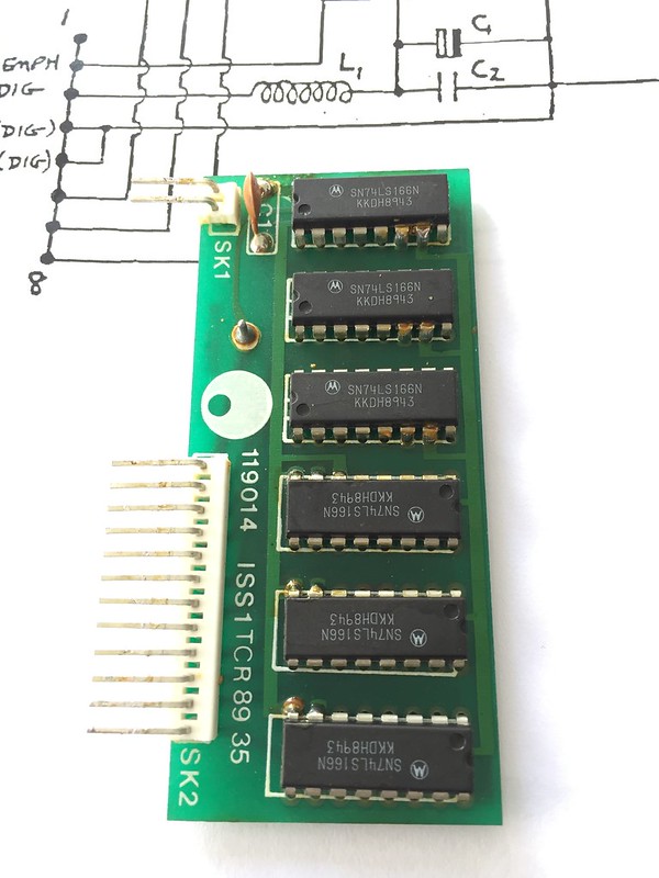
Looks like a re-clocker. It's not in the crude HFE schematic.Tracing it all out (with help from the basic manual on HiFi Engine), the WS, DA and CL all seem to be there from the 7220. They go to that shift register PCB in front of the DAC boards. CL goes to shift register and all 4 DAC boards in a daisy chain. The WS and DA lines go unmodified to the first DAC board, but for the other 3 DAC boards they go to a SN74LS166N chip, and the output of that to the DAC boards.
The original WS and DA signals are much higher amplitude than the outputs from the shift registers (3.5v vs 2v pk-pk), and do not look remotely similar to me. However, they were all the same except one - the DA output for DAC PCB 4, which was 1v pk-pk and a complete mess.
[...]
I could probably swap the register chips around assuming it is only one logic gate that is faulty, and each DAC uses a different output. But the chips are only a £1 each, so I am going to order 6 new ones.
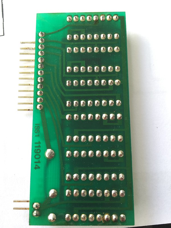
Some more photos
Shift Register PCB (after redoing solder joints);
It's this Dutch Van Ker's fault ...Holy thread resurrection Batman.
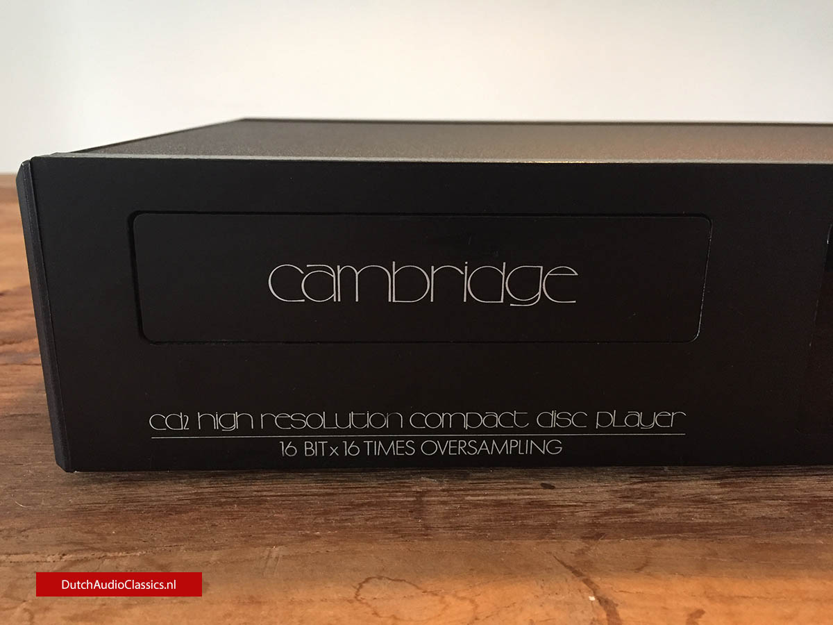
Was the CD3 really a 16x over-sampler? The CD2 has an addit. vertical board (green) full of eight 74 logic ICs. I assume this is 16 x board ??? The CD3 doesn't seem to have a similar board.Just to clarify: the outputs of the DACs are interleaved (hence the 16X oversampling, versus the usual 4X). Since they are current output they can be summed. The reason Stan did 16X was to use minimal filtering on the outputs.
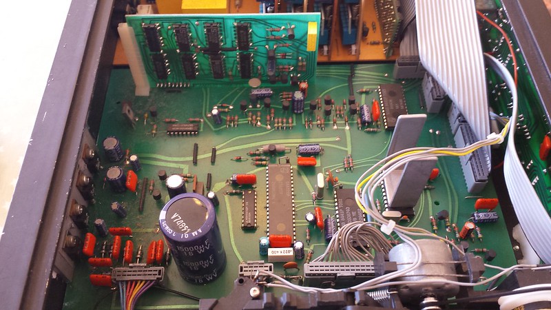
Looking further into the 16x oversampling issue....Was the CD3 really a 16x over-sampler? The CD2 has an addit. vertical board (green) full of eight 74 logic ICs. I assume this is 16 x board ??? The CD3 doesn't seem to have a similar board.
I'm not buyin' it. What I see in the internal photos of both these units -- CD2 and CD3 --as well as that very crude and incomplete hand-drawn schematic (possibly by a service tech by laborious re-tracing) -- just does not "add up" to the 16x OS claim. At this time, the best that best that Japanese could do was 8x (using NPC filters) -- and those were far better researched.Just to clarify: the outputs of the DACs are interleaved (hence the 16X oversampling, versus the usual 4X). Since they are current output they can be summed. The reason Stan did 16X was to use minimal filtering on the outputs.
 dutchaudioclassics.nl
dutchaudioclassics.nl
dutchaudioclassics.nl
If you look at pictures of mine earlier in thread, you’ll see the logic board is there in CD3 too (in front of 4 DAC boards) - a faulty gate in one of the 74x chips was causing my issue.Looking further into the 16x oversampling issue....
Hmmm ... both the CD2 and CD3 had the "16 x 16" label on the front. I think CD2 was from 1988 and CD3 from 1989. Yes?
I'm not buyin' it. What I see in the internal photos of both these units -- CD2 and CD3 --as well as that very crude and incomplete hand-drawn schematic (possibly by a service tech by laborious re-tracing) -- just does not "add up" to the 16x OS claim. At this time, the best that best that Japanese could do was 8x (using NPC filters) -- and those were far better researched.
And in the CD3, that vertical 74ls logic board off the motherboard disappeared but CA still called it 16 x 16.
Methinks the four tda1541 dacs are arranged as follows:
LEFT CH: two parallel stacked tda1541
RIGHT CH: two parallel stacked tda1541
I will stand corrected if one can prove the 16x claim.
REFS:
Cambridge Audio DAC3 & CD3M - 4x Philips TDA1541 - CDM1mkII - DutchAudioClassics.nl
DutchAudioClassics.nl - Cambridge Audio DAC3 & CD3M - 4x Philips TDA1541 - Philips CDM1mkIICambridge Audio CD2 - 4x Philips TDA1541 - DutchAudioClassics.nl
DutchAudioClassics.nl - Cambridge Audio CD2 4x Philips TDA1541 review