
You are using an out of date browser. It may not display this or other websites correctly.
You should upgrade or use an alternative browser.
You should upgrade or use an alternative browser.
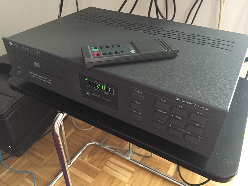
Cambridge Audio CD3...
- Thread starter Dowser
- Start date
Dowser
Learning to bodge again..
The 100uF 35v Rubycon ZLH that I recommended earlier are narrower and will fit if the FC's won't.
Thanks - I've just placed a fresh order, may as well do it nicely
")
Dowser
Learning to bodge again..
Time for an update - in the end I ordered 220uF 16v Rubcons in the end, same size as the 100uF 35v items, but of course a bit close the the -15v rail. Even they were a little too large and required a slight mounting tweak for the middle ones - every single electrolytic now changed (except for that 1uF BP on the servo board);
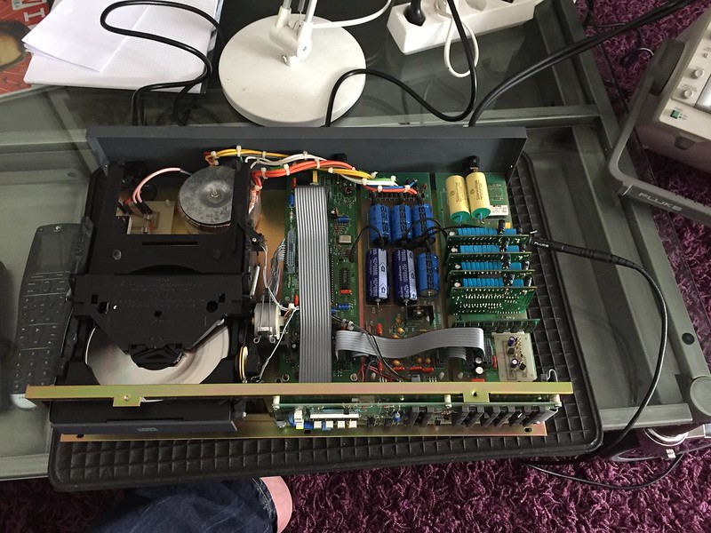
After re-assembly & careful continuity checks I switched it on - all fine...but the original fault of no audio out re-appeared. Digital out looked OK on scope, but I do not have a DAC to test with.
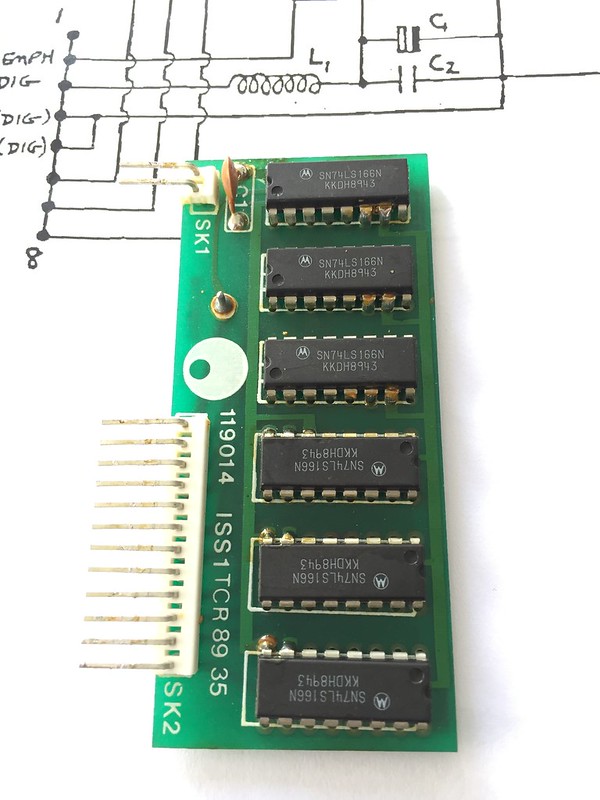
Tracing it all out (with help from the basic manual on HiFi Engine), the WS, DA and CL all seem to be there from the 7220. They go to that shift register PCB in front of the DAC boards. CL goes to shift register and all 4 DAC boards in a daisy chain. The WS and DA lines go unmodified to the first DAC board, but for the other 3 DAC boards they go to a SN74LS166N chip, and the output of that to the DAC boards.
The original WS and DA signals are much higher amplitude than the outputs from the shift registers (3.5v vs 2v pk-pk), and do not look remotely similar to me. However, they were all the same except one - the DA output for DAC PCB 4, which was 1v pk-pk and a complete mess.
So I removed the shift register PCB and DAC boards 3 & 4 (wasn't sure at this stage whether it was a shift register problem, or a faulty DAC) - re-flowed them (although all joints seemed OK) and put them back in, but with boards DAC 3 and 4 reversed.
I got sound for 30 seconds, so thought it must have been a dry joint after all - but then it disappeared. A quick check shows it is still the signal to DAC 4 that is corrupt, so it must be the shift register. Spend 30 minutes looking for a can of freezer spray I know I have somewhere...then use a can of compressed air instead on the suspect chup that does DA for DAC 4. Bingo
I could probably swap the register chips around assuming it is only one logic gate that is faulty, and each DAC uses a different output. But the chips are only a £1 each, so I am going to order 6 new ones.
I still have the faulty display issue - but one time I powered it up and the display operated OK, as did the display off button, but the remote didn't work. Switch it off and on, and the fault returns - display flickering, diplay off and repeat buttons do not work, but remote does. Against my better judgement I'm going to order a new display control chip as well.
Some more photos
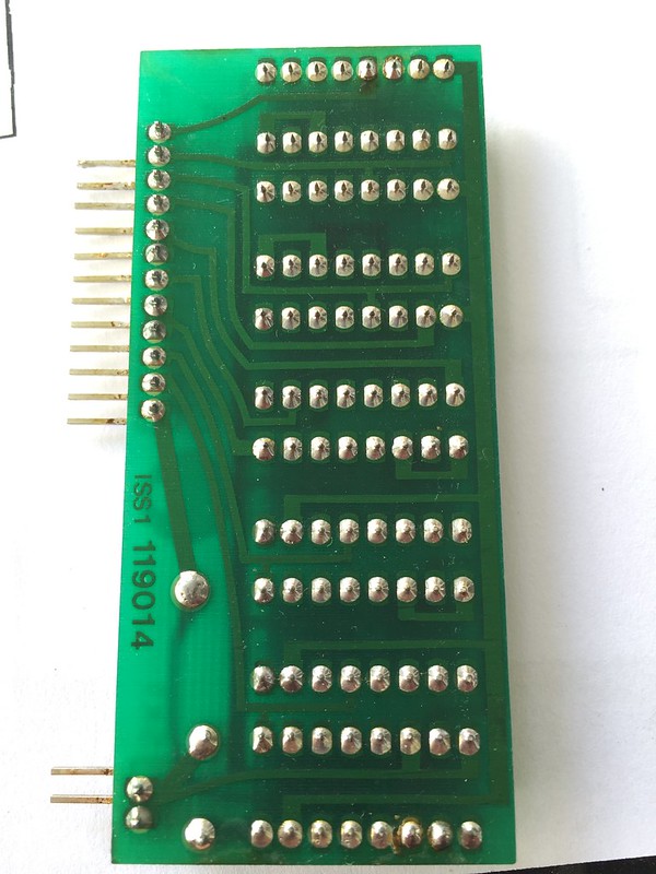
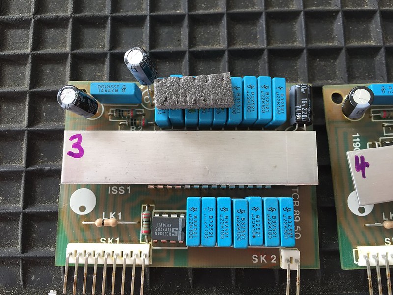
Shift Register PCB (after redoing solder joints);
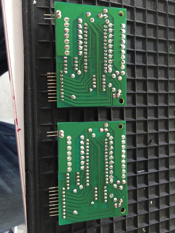
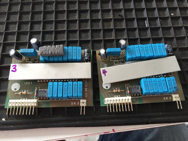
DAC PCBs;
The sound - good, but a bit fatter sound somehow than my reference Woodside. Certainly good enough to look at fitting a Flea to it once it's fully functional
Richard
After re-assembly & careful continuity checks I switched it on - all fine...but the original fault of no audio out re-appeared. Digital out looked OK on scope, but I do not have a DAC to test with.
Tracing it all out (with help from the basic manual on HiFi Engine), the WS, DA and CL all seem to be there from the 7220. They go to that shift register PCB in front of the DAC boards. CL goes to shift register and all 4 DAC boards in a daisy chain. The WS and DA lines go unmodified to the first DAC board, but for the other 3 DAC boards they go to a SN74LS166N chip, and the output of that to the DAC boards.
The original WS and DA signals are much higher amplitude than the outputs from the shift registers (3.5v vs 2v pk-pk), and do not look remotely similar to me. However, they were all the same except one - the DA output for DAC PCB 4, which was 1v pk-pk and a complete mess.
So I removed the shift register PCB and DAC boards 3 & 4 (wasn't sure at this stage whether it was a shift register problem, or a faulty DAC) - re-flowed them (although all joints seemed OK) and put them back in, but with boards DAC 3 and 4 reversed.
I got sound for 30 seconds, so thought it must have been a dry joint after all - but then it disappeared. A quick check shows it is still the signal to DAC 4 that is corrupt, so it must be the shift register. Spend 30 minutes looking for a can of freezer spray I know I have somewhere...then use a can of compressed air instead on the suspect chup that does DA for DAC 4. Bingo
I could probably swap the register chips around assuming it is only one logic gate that is faulty, and each DAC uses a different output. But the chips are only a £1 each, so I am going to order 6 new ones.
I still have the faulty display issue - but one time I powered it up and the display operated OK, as did the display off button, but the remote didn't work. Switch it off and on, and the fault returns - display flickering, diplay off and repeat buttons do not work, but remote does. Against my better judgement I'm going to order a new display control chip as well.
Some more photos
Shift Register PCB (after redoing solder joints);
DAC PCBs;
The sound - good, but a bit fatter sound somehow than my reference Woodside. Certainly good enough to look at fitting a Flea to it once it's fully functional
Richard
Dowser
Learning to bodge again..
Shift register chips changed and I now have reliable audio out. It also seems to sound better, but that may be the caps bedding in - it's still only had about an hour of playing since I swapped them all.
I also ordered the 3 logic chips on the display PCBs in case one was causing my display problem and replaced them at same time. Damned thing worked fine for 5 minutes, and then I stupidly tried changing display from the track to time, and bang it went freaky again
I've got the display processor chip on its way to me from France, I really hope it is that - however unlikely it is for cpu to fail, I really don't see what else it can be. I checked all diodes and transistors today also, all read ok static.
Getting there slowly I soak test it once I finally have it working properly, and then try just a Flea initially to compare it to the Woodside which also has a Flea as its only mod currently (haven't even changed any caps in that yet...).
Richard
I also ordered the 3 logic chips on the display PCBs in case one was causing my display problem and replaced them at same time. Damned thing worked fine for 5 minutes, and then I stupidly tried changing display from the track to time, and bang it went freaky again
I've got the display processor chip on its way to me from France, I really hope it is that - however unlikely it is for cpu to fail, I really don't see what else it can be. I checked all diodes and transistors today also, all read ok static.
Getting there slowly
I soak test it once I finally have it working properly, and then try just a Flea initially to compare it to the Woodside which also has a Flea as its only mod currently (haven't even changed any caps in that yet...).Richard
Dowser
Learning to bodge again..
Wow - a couple more hours of playing and it is doing some really good stuff now. Ultimate high and low frequency definition not as good as Woodside, but frequency around vocals just boogies - great imaging! I tried powering it off and back on a few times in hope the display works long enough for me to put the damn thing in repeat (when display freaks, then some of the buttons stop working too) and leave it running overnight...no luck yet
chiily
PFM Special Builder
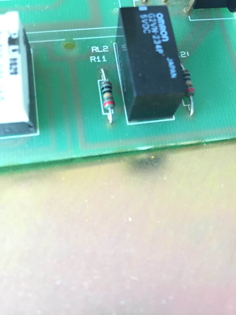
6 band resistor - I think this is 1K?!
Many thanks, Richard
Brown-Black-Black-Yellow(??)-Brown-Red is 1M 1% 50ppm
Brown-Black-Black-Gold(??)-Brown-Red is 10R 1% 50ppm
Brown-Black-Black-Brown-Brown-Red would be 1k 1% 50ppm
Dowser
Learning to bodge again..
Thanks Garf - missed your post. I just leave them as is, and have given myself the task on a nice rainy day to understand 6 band colour codes!
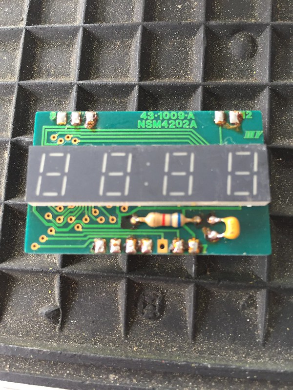
Update: DOH - it wasn't the display processor, should have done some investigation before ordering...as always...it's never the processor
Everyone says the NSM4202A display module gives problems, especially on the Cambridge designs as it is overdriven a bit (display too bright) - I just assumed, because the "display off" button wasn't working, it couldn't be that (and, on the one or 2 times it has worked OK, all display segments were OK).
So, tracing circuit for display off switch, I find it switching OK up to a blocking diode - other side of the diode was at a constant voltage, even though otherside of it was switching nicely when using the switch.
There's a few other components the other side of the diode, I couldn't really work it out to be honest But ultimately I decided to pull the display unit out and try again - voltage acts correctly all the way to the display pin without it in cct...I guess something has shorted on the display PCB.
Anyhow - anyone got one of these? Either that or I follow the repair procedure I linked to earlier from DIY Audio.
Getting there...but too slowly
Richard
Update: DOH - it wasn't the display processor, should have done some investigation before ordering...as always...it's never the processor
Everyone says the NSM4202A display module gives problems, especially on the Cambridge designs as it is overdriven a bit (display too bright) - I just assumed, because the "display off" button wasn't working, it couldn't be that (and, on the one or 2 times it has worked OK, all display segments were OK).
So, tracing circuit for display off switch, I find it switching OK up to a blocking diode - other side of the diode was at a constant voltage, even though otherside of it was switching nicely when using the switch.
There's a few other components the other side of the diode, I couldn't really work it out to be honest
But ultimately I decided to pull the display unit out and try again - voltage acts correctly all the way to the display pin without it in cct...I guess something has shorted on the display PCB.Anyhow - anyone got one of these? Either that or I follow the repair procedure I linked to earlier from DIY Audio.
Getting there...but too slowly
Richard
bramjacobse
New Member
Hi,
I have made some Drop-in replacement for the NSM4202 en NSM4202a
With 7segment display or smd-leds..


Please check http://forum.mfbfreaks.com/viewtopic.php?f=7&t=9559
Regards Bram Jacobse
I have made some Drop-in replacement for the NSM4202 en NSM4202a
With 7segment display or smd-leds..
Please check http://forum.mfbfreaks.com/viewtopic.php?f=7&t=9559
Regards Bram Jacobse
Dowser
Learning to bodge again..
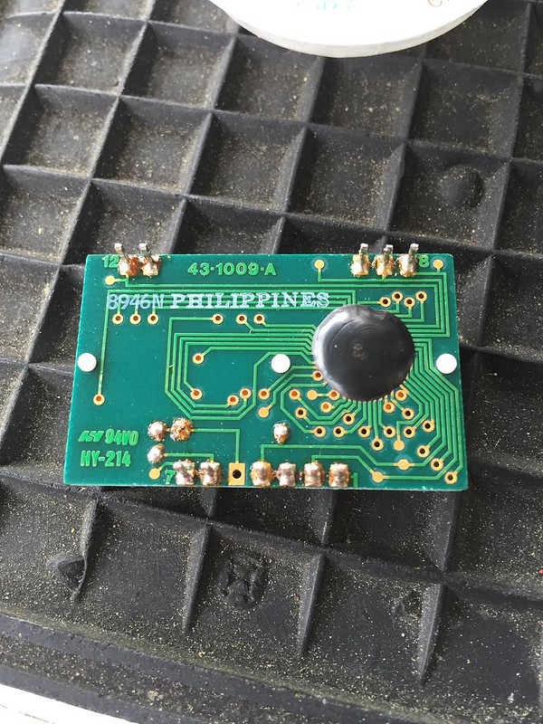
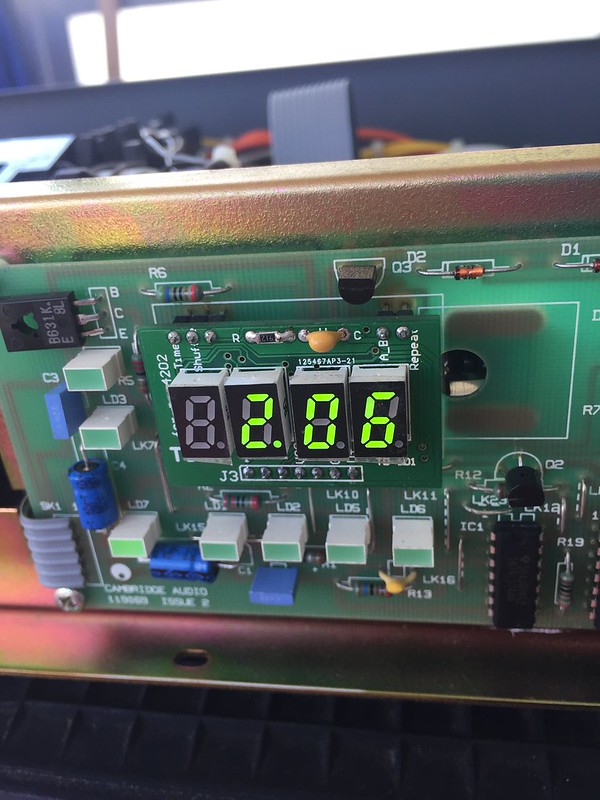
Dammit - this thing is driving me to hell New display arrived, it is not original equipment, but a (nice) repro. I noticed before mounting it that the chip on the back meant it would sit around 2mm further out than the OE display, but figured the original front panel would have enough tolerance that this wouldn't be a problem. What I missed was that the LED banks are also much thicker than stock, so it's actually 5-6mm thicker than the stock item. Works perfectly, but I cannot remount front panel as it fouls the display glass... F*ck
So now I need to either use the link above to repair the stock item with a new IC, find a donor 160 type Philips machine (not 150, their NSM display is slightly different) or check the link above to see how deep it is. Goddam it, I will have this player fully functional again...and with it's covers on!
Pictures - 2 displays front side;
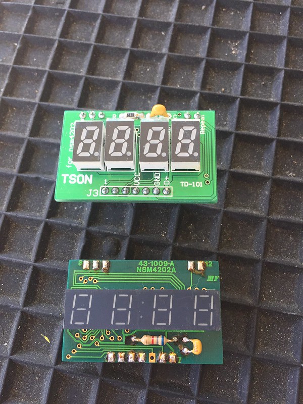
Back;
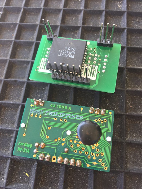
Mounted and working...yay <very-lower-case>;
Richard
New display arrived, it is not original equipment, but a (nice) repro. I noticed before mounting it that the chip on the back meant it would sit around 2mm further out than the OE display, but figured the original front panel would have enough tolerance that this wouldn't be a problem. What I missed was that the LED banks are also much thicker than stock, so it's actually 5-6mm thicker than the stock item. Works perfectly, but I cannot remount front panel as it fouls the display glass... F*ck So now I need to either use the link above to repair the stock item with a new IC, find a donor 160 type Philips machine (not 150, their NSM display is slightly different) or check the link above to see how deep it is. Goddam it, I will have this player fully functional again...and with it's covers on!
Pictures - 2 displays front side;
Back;
Mounted and working...yay <very-lower-case>;
Richard
Mike P
Trade: Pickwell Audio
Hi Richard,
How are you getting on with the display repair/replacement?
No harm in doing a bit of op amp rolling but I wouldn't be too hasty to remove those 5534's. I've auditioned lots of op amps in my Sony 555ESD and I'm still happily using 5534's in one of the positions.
Something worth noting is that I've found that the various types of 5534's available sound quite different to one another and it is well worth trying a few different types. My favourites so far are the Signetics NE5534AN.
Dowser
Learning to bodge again..
Thanks Mike
Plan is to use it stock for a while - the 5534s seem a bit weird in this cct, there are barely any passive components around them. I post a cct diagram once I have it fully functional and bedded in.
I'm currently in touch with seller of the non-OE display, he has ordered some NOS originals from Philipines which I hope will get to him this week, so he can ship me one (he has noted same issue on some CDPs - works perfectly but 5mm out of spec, OK on Philips machines but not on Cambridge).
Plan is to use it stock for a while - the 5534s seem a bit weird in this cct, there are barely any passive components around them. I post a cct diagram once I have it fully functional and bedded in.
I'm currently in touch with seller of the non-OE display, he has ordered some NOS originals from Philipines which I hope will get to him this week, so he can ship me one (he has noted same issue on some CDPs - works perfectly but 5mm out of spec, OK on Philips machines but not on Cambridge
).Dowser
Learning to bodge again..
After banging my head against my 2 faulty Naim CDi's for last few weeks (making progress, but both still faulty...), I decided I needed a bit of positive outcome, so finally fitted the OE replacement from the original seller into the CD3 and boxed it up.
So, it is now completely stock except Schottky rectifier diodes and slightly increased decoupling around the 4x TDA1541As. Every single electrolytic has been replaced (except one on servo board, and 2 on output time delay PCB), and faulty shift-register chip and display module replaced.
Sounds lovely in that slightly big and bouncy way (compared to a single TDA based DAC) - I'm going to leave it in the system for a while now before deciding what to do next. It will be either sell as stock or keep it and start modding it - a lot will depend how I go with the damned Naim's
Richard
massimo pascale
Member
I know it's an old topic, but....
my Cambridge CD3 transport has a burnt resistor (R25) in the display control board. Didn't find any schematic on internet. Any suggestion'd be appreciated..
Massimo
my Cambridge CD3 transport has a burnt resistor (R25) in the display control board. Didn't find any schematic on internet. Any suggestion'd be appreciated..
Massimo