advertisement


building +5V ALWSR and doubts

geoturbo

tinkerer w/o highly evolved auditory stimulus cpu
Dear Gents,
my very first thread on PFM about my first ALWSR +ve build and for some questions related for the better safe than sorry's sake.. Been reading overnights about the assembly test and application manual, sourced all components for this +5V ALWSR (Panasonic NHG caps and MRS25 resistors), weller soldering iron's hot and all is ready to go... btw this is going to power my nice and old diy DAC based on CS4397 chip.

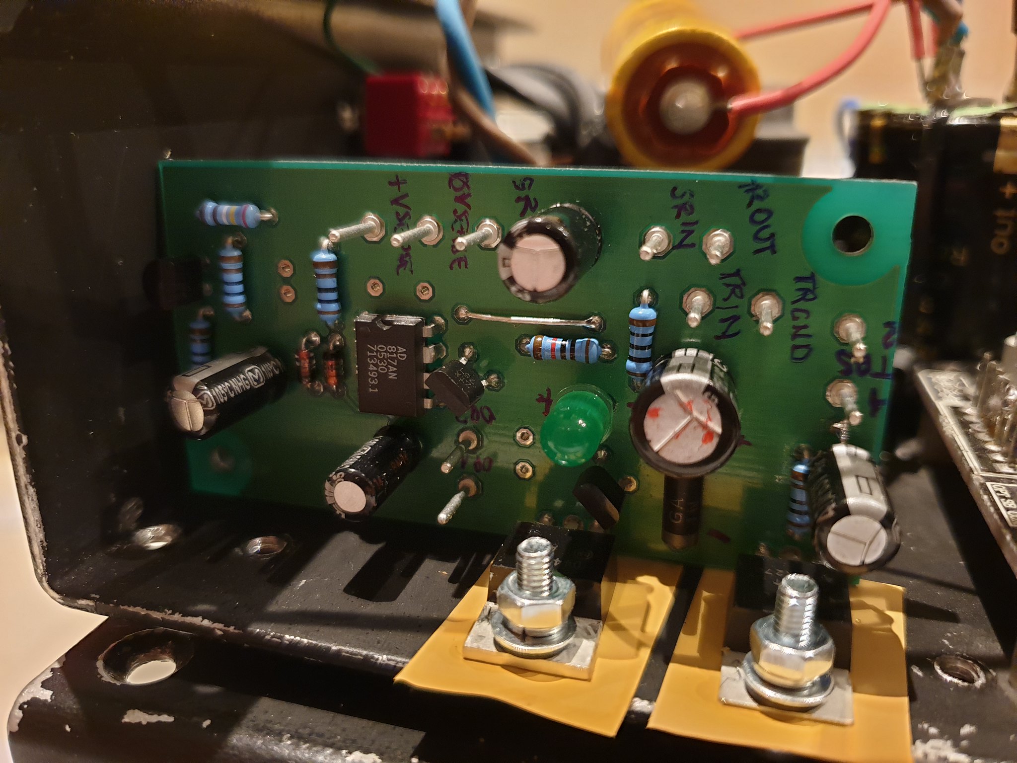
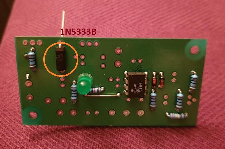
I soldered the low components - gladly the AD817AN had been soldered already - and now I am in the process of soldering the 1N5333B zener.

Could anyone gently confirm if the 1N5333B is set correctly in place as shown in the picture?

Thanks a lot

49451069072_b25886358e_c.jpg
 
A red or green LED would be a slightly better choice than the 3.3volt zener, particularly as zeners have a poor tolerance. If you have a spare green LED I would use that. Also its hard to see for sure but it looks like the flat face of the green LED is facing towards the opamp, which means it is the wrong way round. If it is in fact facing away from the opamp, then it is correct.

John
 
That's great Martin, thanks, 1N5333B is now firm in its place.

John, thanks for your suggestion. I wonder if it would be hard to desolder the 1N5333B zener.. but I'll try to resist the itch for now and consider this for the next builds and/or improvements (don't talk me into vbe territory for now.. :) ). 1N5333B from specs is having a 5% voltage tolerance and as far as I read in the manual this component (D2) is part of the start-up process.

I am pretty sure I soldered the led (D1) the correct way round, with the plus from its longer leg facing the opamp. Its body does not do justice as It has no flat face, but I'll doublecheck just in case and update.. thanks for your suggestions As well.
 
D1 is the correct way round, flat surface (must have been very tired for not having seen It last night..) is facing away from opamp, going on slow some caps have been installed.

By the way, I seem to read that C5 cap is important for stability but in the part list this is Stated As "Not Fitted" so I Guess It is ok to leave this out, isn't it?
 
It feels good, thanks, @Worive

ALWSR's now installed and I will hopefully will be able to test it soon for good.
Psu's giving 12,10V of raw DC out of smoothing CAP with no load.

49467193148_bf04930e68_k.jpg
 
Neat and orderly way to doing things, documenting the build to yourself on the pcb like that is a great idea. Not just for the initial build and test but very especially when you might have cause to look inside the case in a few years' time for any reason, having forgotten all about it.

Hope you get the results you seek!
 
BTW C5 isn't important at all for stability; the ALWSR is fine without it by design.
And decoupling caps like that belong right at the load they serve, not the output of a reg like this - that's why it's not fitted.
 
So kind, Martin.

I tested the pre-reg, It was outputting oscillating voltages at first, repassed the soderings and its output was then fixed to 3,2V (manual states thjs should be' 2,5V, hoping I can stick and consider 3,2V as normal.. ).

Tested the super reg and It is outputting 4,9V with no load. Guess it is about time to connect it to the DAC! Fingers crossed.

Which wiring scheme should I consider for sensing? Remote sensing?
 
The 2.5v above Vout from the pre-reg is dependant on both R1 and R2. R2 appears hidden under its decoupling cap on the bottom right of the picture so I can't see it (possibly on the reverse of the board?) but it should be the same value as R1 for the 2.5v. BTW you can get a small improvement in pre-reg performance by replacing R2 with a red LED. You do lose about 0.35 volts of dropout voltage for the whole regulator but I think it worthwhile if you have an LED available.

I normally run the reg with local sense first and then change (upgrade) to remote once I'm sure all is working. For remote sense the current loops have to be kept small (twisting of wires) but you can make use of the wires already installed which helps in getting the lengths right.

John
 
I doublechecked the resistor values and R2&R3 (as per schematic) are both 1K. R3 is on the reverse of the board.

Would a green led work in place of R3 or Is a red one needed?

I connected the ALWSR to my DAC with local sense and It worked! Ooops for roughly 4 minutes only.. output voltage gets gradually changing until it drops suddenly to 2,5V and DAC board turns off and remaining at 2,5V.
There seem not to be any damaged component so far.

Output wires are not crossed.. will try with that next.. but I doubt this will solve the Issue.. any further ideas? A Symptom of too low ESR of input Cap maybe?
 
A basic green led will run around 1.9 - 1.95v at the setpoint current; a red led, about 0.3v lower.

If you have enough over head / raw supply going in, a cheap green led will run just fine - i.e: at total cost of about +0.6v over nominal required in raw supply, or say 11vdc min input. If you raw supply under the same total load current is 12vDC or better = just fine.
(nb these are based on 'very cheap, old school' LEDs - not modern high-brightness types)
 
Thanks for the upgrades, I'm noting them and will be possibly trying them out when all is working well..

I have 11,2VDC after the smoothing cap, the tracking pre-regulator is outputting stable 2,55V under load.

The super regulator output is not stable though. It is set at 4,9V at the turn on but then drops to 2,75V after a minute, some minutes or ready from the turn on.. I wonder what could cause this..

One silly question.. do components need to be soldered on both sides of the board? I tried my best to solder them but applied heat on the bottom side only.
 
I have 11,2VDC after the smoothing cap, the tracking pre-regulator is outputting stable 2,55V under load.

The super regulator output is not stable though. It is set at 4,9V at the turn on but then drops to 2,75V after a minute, some minutes or ready from the turn on.. I wonder what could cause this..

Is this with the super-reg not connected to any load?
The opamp and superreg reference are enough of a load to ensure the pre-reg drops into regulation (c 10mA load on it) but really you need a similar small minimum load on the output for the super-reg portion to be able to get properly into regulation. 5v out / 10mA load = say maximum 470ohm resistor tacked across the output; but whatever you have to hand - 220, 100 ohm all good.
 
BTW, the other reason C5 isn't fitted on the board is that it is in parallel with C3, the decoupling cap for the opamp, which is always fitted. When I mod an ALWSR for a higher voltage application I cut a track and feed C3 through a small resistor of say 220 ohms. This drops a volt or so but adds extra isolation for the opamp and leaves just the capacitor at the load sitting across the ouput.
 
@martin clark voltage drop happens without load, when connected to the DAC board and also when connected to a dummy load (made a test with 499ohm resistor). I also tried with a higher transformer for about 18V after smoothing Cap but problem stays the same.

I was concerned about C1 having too low ESR (I read about It somewhere in older ALWSR threads) and tried to pull up a leg of C1 and added a 0,34ohm series resistance, but output voltage drop is not cured. Same drop issue.

Trying to shoot questions from what I observe more than what I understand so bear with me.. My next question would be whether It is correct that the D1 led is not very Bright. Same intensity remains when voltage output is regular 4,9V or when dropping to 2,75V..
 
I'm thinking that to help separate things out a bit, try powering the super reg directly, without the pre-reg connected, just to help locate where the problem lies. These are always a bit of a bugger to debug, as the whole bootstrapped nature makes separation of circuit elements tricky.
 
Tbh the parts count is not that great and the cost not high either...
When mine were playing silly buggers I just replaced every thing on the boards ...bar the resistors...which all looked good ....so diodes caps tranny's and IC
Sorted the problem and saved my sanity trying to fault find a bootlegged circuit ...
 
Well that's a brute force and expensive route, when simply finding-out why is 1. more good DIY time and 2. as a result, instructive ;)


[OT example: having recently nailed-together a simple discrete variable-output, linear-reg bench supply out of the contents of the scrap box for c.0-22v at 5A, up to c.8A possible as a 'thing that I could probably use out of this pile of bits'... working out why it shut down early in some load conditions has been useful & fun as a Saturday-teatime exercise ... and swapping parts would not have fixed it. The basic idea was right, the implementation not so much. I learned some things ;) ]


advertisement


Back
Top